Optical pickup actuator

a technology of optical pickup and actuator, which is applied in the direction of mountings, instruments, data recording, etc., can solve the problems of increased aberration, different lens holders, and cracked objects, so as to enhance the bonding force of objects, block out heat, and minimize heat transmission.

Active Publication Date: 2009-05-19
IONOSEP X HLDG
View PDF18 Cites 4 Cited by
  • Summary
  • Abstract
  • Description
  • Claims
  • Application Information

AI Technical Summary

Benefits of technology

[0024]An object of the present invention is to provide an optical pickup actuator that can minimize the transmission of heat from coils to an object lens by forming recessed portions on side surfaces of a lens holder.
[0025]Another object of the present invention is to provide an optical pickup actuator that can block out heat that is transmitted from coils to an object lens by processing heat discharge grooves on a lens-seating portion surrounding a beam-passing hole.
[0026]Still another object of the present invention is to provide an optical pickup actuator that can enhance a bonding force of an object lens by improving a bonding structure between a lens holder and the object lens.

Problems solved by technology

When the heat generated by the coils is transmitted to the object lens for a long time, the aberration is increased.
Furthermore, when excessive electric current is applied to the coils, the object lens may be cracked due to a thermal-stress.
Also, in a high speed optical pickup actuator, even when the object lens is attached to the lens holder using adhesive, the lens holder may be different in a frequency response from the object lens since the adhesive force is not enough.

Method used


Image

  • Optical pickup actuator
  • Optical pickup actuator
  • Optical pickup actuator

Examples


Embodiment Construction

[0035]Reference will now be made in detail to the preferred embodiments of the present invention, examples of which are illustrated in the accompanying drawings. Wherever possible, the same reference numbers will be used throughout the drawings to refer to the same or like parts.

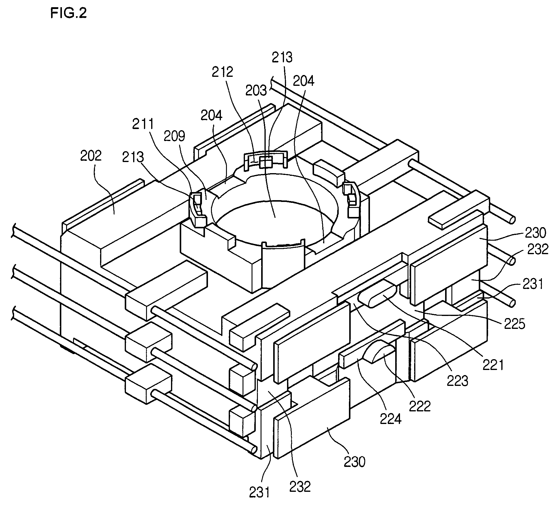
[0036]FIGS. 2 through 4 are views illustrating an optical pickup actuator according to an embodiment of the present invention.

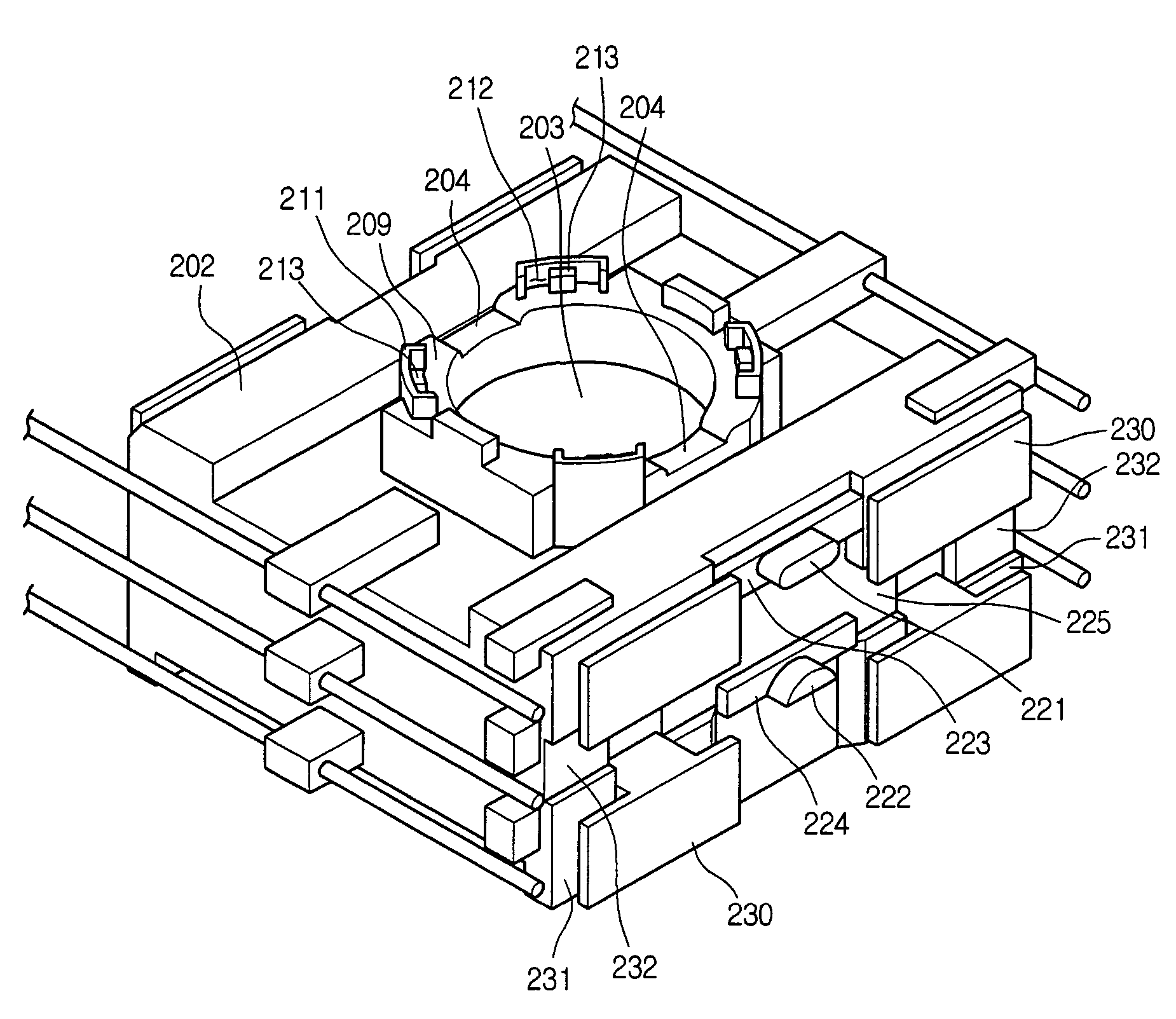
[0037]Referring to FIGS. 2 through 4, a lens holder 202 has first heat dissipation grooves 204 formed on a lens-seating portion 209 on which an object lens 201 seats, second heat dissipation grooves 225 formed on centers of opposite side surfaces of the lens holder 202, and third heat dissipation grooves 232 formed on left and right portions of each of the opposite side surfaces of the lens holder 202.

[0038]The object lens 201 seating on the lens-seating portion 209 is aligned with a beam-passing hole 203 surrounded by the lens-seating portion 209. Lens guide portions 211 protrude fro...


PUM

PropertyMeasurementUnit
distanceaaaaaaaaaa
electric currentaaaaaaaaaa
outer circumferenceaaaaaaaaaa

Abstract

There is provided an optical pickup actuator for actuating a lens holder having an object lens according to an interaction between coils and magnets. The optical pickup actuator includes a lens-seating portion formed on the lens holder to support the object lens and a lens guide portion protruding from the lens-seating portion to securely support the object lens. The lens guide portion has an adhesive confining groove in which adhesive can be injected to securely fix the object lens.

Description

BACKGROUND OF THE INVENTION[0001]1. Field of the Invention[0002]The present invention relates to an optical pickup actuator for reading and writing data from and to an optical recording medium.[0003]2. Description of the Related Art[0004]The optical pickup actuator maintains a relative location between an object lens and an optical recording medium at a predetermined distance by moving a moving part on which the object lens is mounted and reads and writes information from and to the optical recording medium by following a track of the optical recording medium.[0005]The optical pickup actuator has a permanent magnet and a coil. When the electric current is applied to the coil, the optical pickup actuator moves the object lens to a desired location. At this point, the moving part moves in focusing and tracking directions that are perpendicular to each other.[0006]FIGS. 1A and 1B are schematic views of an optical pickup actuator according to the related art.[0007]Referring to FIGS. 1A ...

Claims


Application Information

Patent Timeline
Patent Type & Authority Patents(United States)
IPC IPC(8): G02B7/02
CPCG02B7/023G02B7/025Y10T29/49826
Inventor CHOI, IN HOHONG, SAM NYOLKIM, JIN AKIM, YOUNG JOONG
Owner IONOSEP X HLDG
Why Eureka
Try Eureka