Wide frequency range signal generator and method, and integrated circuit test system using same

a signal generator and wide frequency range technology, applied in the field of generating signals, can solve the problems of a single vco, a relative complex and expensive solution, and achieve the effect of reducing the cost of implementation and maintenan

Active Publication Date: 2009-05-19
MICRON TECH INC
View PDF12 Cites 0 Cited by
  • Summary
  • Abstract
  • Description
  • Claims
  • Application Information

AI Technical Summary

Problems solved by technology

However, conventional VCO's are generally able to operate over only a limited range of frequencies.
While this approach addresses the shortcomings of using a single VCO, it results in a relatively complex and expensive solution to the limitations inherent in using a single VCO.

Method used


Image

  • Wide frequency range signal generator and method, and integrated circuit test system using same
  • Wide frequency range signal generator and method, and integrated circuit test system using same
  • Wide frequency range signal generator and method, and integrated circuit test system using same

Examples


Embodiment Construction

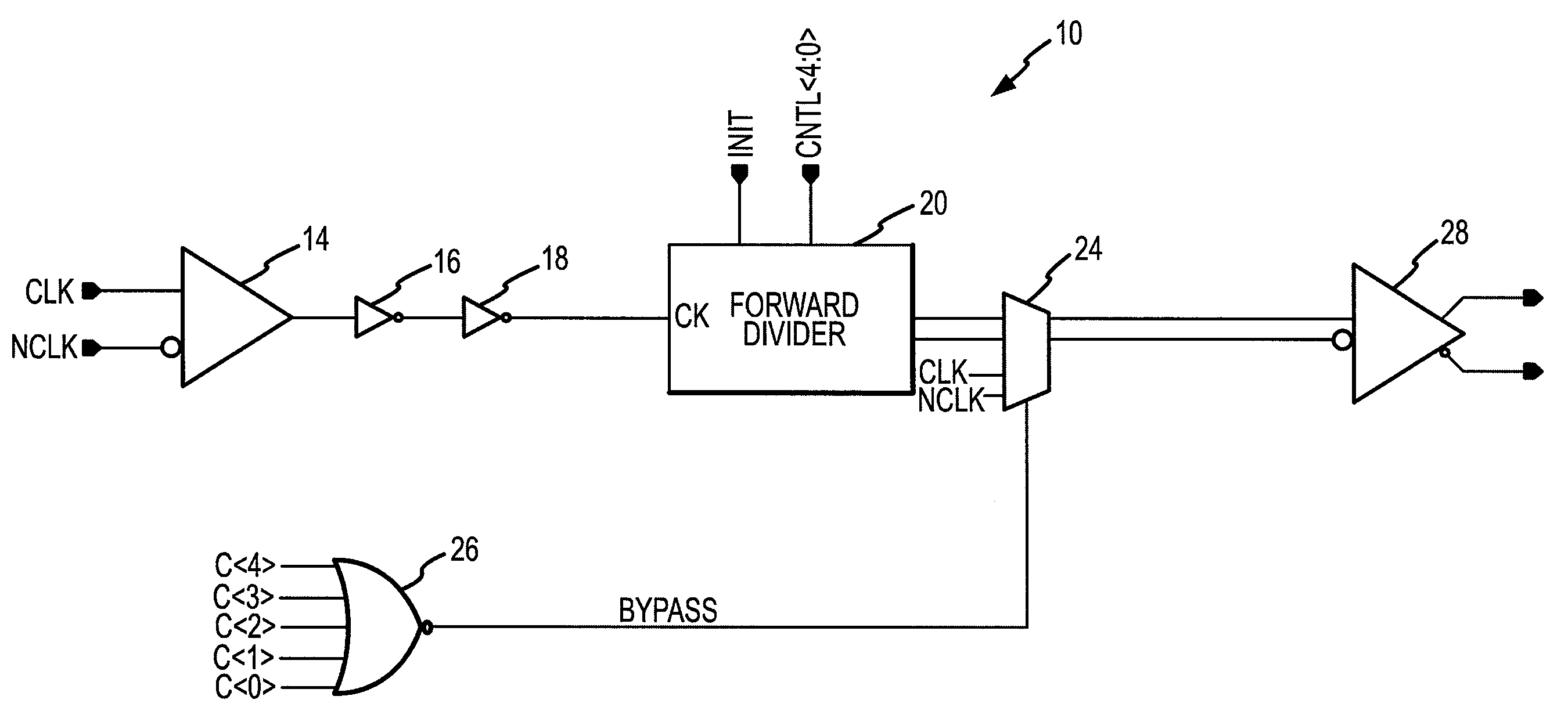
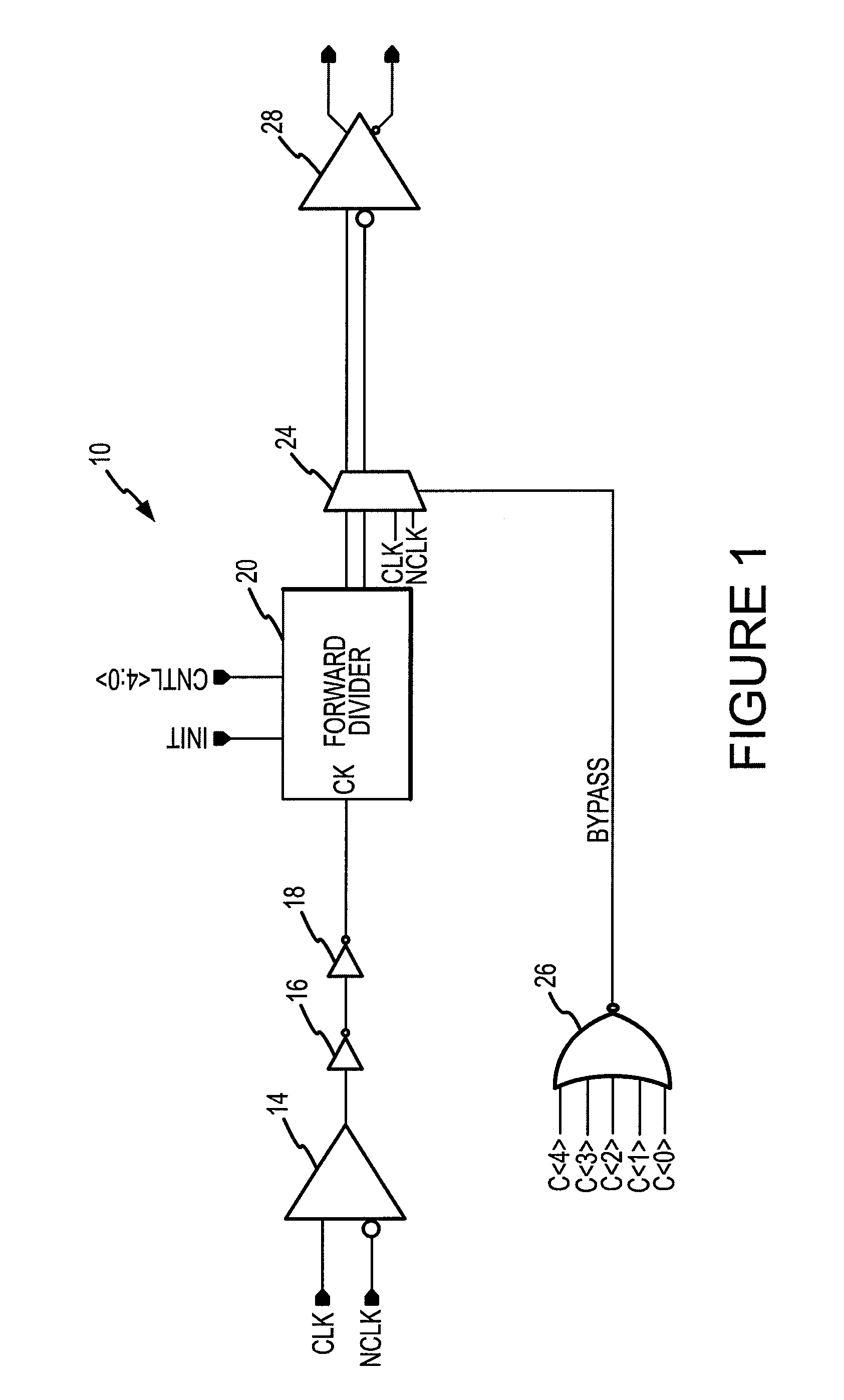
[0017]A periodic signal generator 10 according to one example of the invention is shown in FIG. 1. The signal generator 10 includes a differential amplifier 14 receiving complimentary clock signals CLK, nCLK and generating a corresponding single-ended output signal. (Signal names used herein that are prefaced by a “n” are active low). Because of capacitance and attenuation in a signal line coupling the CLK and nCLK signals to the amplifier 14, the CLK and nCLK signals may not fully transition between logic levels. The differential amplifier 14 amplifies the CLK and nCLK signals so that the signal at the output of the amplifier 14 fully transitions between logic levels, such as ground and a supply voltage VCC. In another example of the signal generator 10, a single ended clock signal is applied to either a buffer (not shown) or one input of the amplifier 14, with the other input being connected to ground.

[0018]The output of the differential amplifier 14 is coupled through two inverte...


PUM


Abstract

A signal generator produces an output clock signal by coupling an input clock signal through a plurality of divider circuits each of which is formed by a toggling flip-flop. The frequency of the output clock signal is adjusted by selecting the flip-flop to which the input clock signal is coupled. Retimer flip-flops may be coupled between adjacent flip-flips to resynchronize the signal being coupled through the flip-flops. Each of the retimer flip-flops receives a respective signal from the output of an upstream flip-flop at its data input, and it receives the input clock signal at its clock input. The flip-flop then applies the signal to a downstream flip-flop in synchronism with the input clock signal. The final two flip-flops through which the input signal is coupled may be preset to various states to set the phase of the output clock signal to one of four phases.

Description

TECHNICAL FIELD[0001]This invention relates to generating signals for testing and other purposes, and, more particularly, to a system and method for generating a periodic signal over a wide range of frequencies for testing integrated circuits and for other purposes.BACKGROUND OF THE INVENTION[0002]During the fabrication of integrated circuits such as memory devices, it is conventional to test such integrated circuits at several stages during the fabrication process. For example, the integrated circuits are normally connected to a tester with a probe card when the integrated circuits are still in wafer form. In a final test occurring after the integrated circuits have been diced from the wafer and packaged, the integrated circuits are placed into sockets on a load board. The load board is then placed on a test head, typically by a robotic handler. The test head makes electrical contact with conductors on the load board that are connected to the integrated circuits. The test head is c...

Claims


Application Information

Patent Timeline
Patent Type & Authority Patents(United States)
IPC IPC(8): G01R31/28
CPCG01R31/31922G06F1/08G11C29/56G11C29/56012H03K23/002
Inventor RAUSCH, GREGRABE, ROBKLIER, JAKE
Owner MICRON TECH INC
Why Eureka
Try Eureka