Valve and auxiliary exhaust system for high efficiency steam engines and compressed gas motors

a steam engine and compressed gas technology, applied in the field of steam engines, can solve the problem of more steam passing through the engine, and achieve the effect of improving the operation control

Active Publication Date: 2009-05-26
PRITCHARD EDWARD
View PDF21 Cites 4 Cited by
  • Summary
  • Abstract
  • Description
  • Claims
  • Application Information

AI Technical Summary

Benefits of technology

[0017]It should be noted that the device as herein disclosed shows employment for use in combination with a fixed timing engine for ease of illustration of the novel properties of the device and the great utility provided in steam or compressed air engines. However, those skilled in the art will no doubt realize that inclusion of a means to vary engine timing, such as a camshaft, could be added to the design disclosed herein, thereby providing a variable timing engine with improved efficiency, and all such modifications are anticipated to be within the scope of this invention.
[0019]The embodiment further provides for built-in easy starting with low compression plus phasing out auxiliary exhaust under more load and speed. This is achieved with the area of the auxiliary exhaust ports designed so that, on start-up and at slow speeds, the steam flow is adequate to hold cylinder exhaust pressure close to exhaust pipe discharge pressure. This assists with easy starting of the engine and makes for smooth running at low speeds. However, with rising speeds and bigger throttle openings, more steam will pass through the engine. There will consequently be greater pressure drop through the auxiliary exhaust ports with the amount of pressure drop depending on the flow areas. The latter are designed to achieve the desired metering of the steam flows. This will lead to higher cylinder pressures and higher compression pressures, i.e., the engine will run more like a “full uniflow” type and higher efficiency can be realized.
[0025]It is another object of this invention to supply the disclosed steam engine wherein two areas of the slide valve providing improved operation control steam flow through separate adjacently located inlet and auxiliary exhaust ports and passages.
[0026]It is another object of this invention to supply an improved steam engine providing a slide valve control of overall operation which is much simpler than alternative systems of controlling the extent and timing of opening of the auxiliary exhaust ports.

Problems solved by technology

However, with rising speeds and bigger throttle openings, more steam will pass through the engine.

Method used


Image

  • Valve and auxiliary exhaust system for high efficiency steam engines and compressed gas motors
  • Valve and auxiliary exhaust system for high efficiency steam engines and compressed gas motors
  • Valve and auxiliary exhaust system for high efficiency steam engines and compressed gas motors

Examples


Embodiment Construction

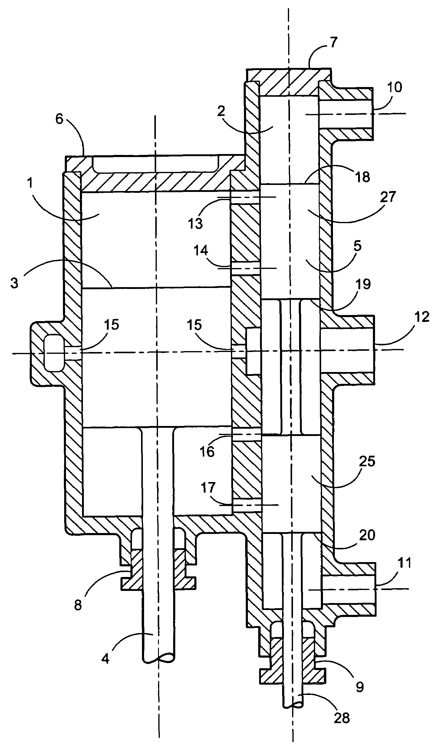
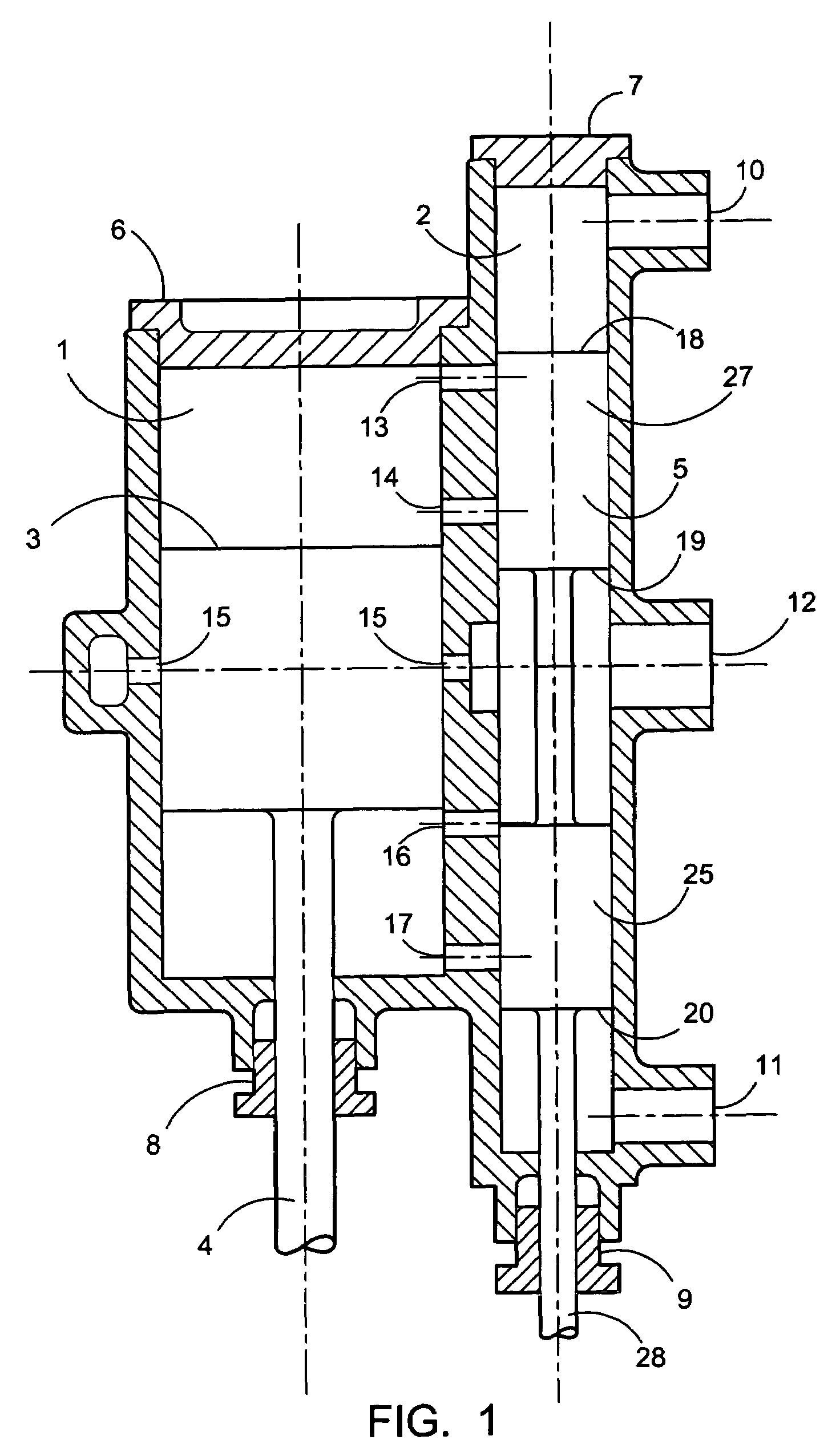
[0031]FIG. 1, shows the cylinder arrangement for an embodiment of the device for employment with a uniflow double-acting steam engine including the herein disclosed and described novel valve design, which used in conjunction with a conventional harmonic valve drive mechanism, forms the main part of this invention. Not shown is the crankcase containing the connecting rod, crosshead, valve motion and other attendant parts of the engine for which the disclosed device is adapted for engagement. These latter parts may be conventional in design.

[0032]The main parts shown are the cylinder 1, the valve chest 2, and the piston, 3, which would best be fitted with piston rings (not shown). Also shown in FIG. 1 is the piston rod 4, and the slide valve 5, showing the continuous exterior surface to contact the valve chest and which also would be fitted with sealing rings but which are not shown. Number 6 depicts the cylinder head and the valve chest cap is shown as number 7. The piston rod sealin...


PUM


Abstract

A steam engine with improved intake and exhaust flow provided by separate pairs of intake and exhaust ports located at both ends of a steam drive cylinder. A slide valve located adjacent to the drive cylinder provides for timed sealing of intake and exhaust ports during operation. Exhaust is facilitated by the provision of two paths of exhaust from the cylinder and the exhaust ports may be adjusted for a flow volume to meter exhaust steam flow to significantly reduce back pressure only at low speeds of said engine.

Description

[0001]This application claims the benefit of U.S. Provisional Patent Application No. 60 / 651,693, filed Feb. 9, 2005.FIELD OF THE INVENTION[0002]The invention relates to steam engines. More particularly, the invention herein disclosed relates to an improved design of the valve and auxiliary exhaust system for steam engines of both the double-acting and single-acting designs and in particular for uniflow steam engines with auxiliary exhaust. The design can be employed upon fixed timing engines or with added means for timing adjustment, upon variable timing steam engines.BACKGROUND OF THE INVENTION[0003]Single-acting and double-acting steam engines have provided power for industry and other uses for a long period of time. The single-acting steam engine may resemble a two and a four-stroke internal combustion engines in that a piston, connecting rod and crank are used per cylinder set. With the double-acting form of steam engine, straight line reciprocating motion is described not only ...

Claims


Application Information

Patent Timeline
Patent Type & Authority Patents(United States)
IPC IPC(8): F01L31/00
CPCF01B17/04F01L15/10F01L21/02F02C1/00F02C1/105
Inventor PRITCHARD, EDWARD
Owner PRITCHARD EDWARD
Why Eureka
Try Eureka