Elevator installation with individually movable elevator cars and method for operating such an elevator installation

a technology of elevator cars and elevators, applied in elevators, agricultural tools and machines, instruments, etc., can solve the problems of difficult to adjust the elevator car, difficult to move the elevator car, etc., and achieve the effect of great flexibility in the preparation and movement of the elevator car

Active Publication Date: 2009-05-26
INVENTIO AG
View PDF22 Cites 36 Cited by
  • Summary
  • Abstract
  • Description
  • Claims
  • Application Information

AI Technical Summary

Benefits of technology

[0011]The present invention is based on the fact that the process of loading and unloading elevator cars, which in itself is relatively time-consuming, can take place in such manner that at least two elevator cars can be loaded / unloaded more or less simultaneously. At the same time, great flexibility of readying and moving the elevator cars is made possible in that a plurality of elevator cars is employed which are, or can be, individually driven, and can therefore move in the elevator installation independent of each other.

Problems solved by technology

It is a disadvantage of the known elevators with several elevator hoistways that changing hoistways mechanically is very complex and in many cases proceeds only slowly.
Consequently, when the amount of traffic is high, the handling capacity is limited.
However, it has become apparent that a method with double-deck cars also brings disadvantages.
Such disadvantages are that such an elevator installation cannot be deployed flexibly because the entire double-deck car must always be moved even if only a small transportation capacity is necessary, and that both car decks must interrupt their travel if a halt needs to be made at a floor for passengers of one car deck.
In many cases, the distance between the individual floors is not equal, which requires complex measures on the double-deck car.
It is a disadvantage of the known elevator installations with several elevator cars traveling in one hoistway that the transportation capacity is limited by a relatively small number of elevator cars departing from a main stop per unit of time.

Method used


Image

  • Elevator installation with individually movable elevator cars and method for operating such an elevator installation
  • Elevator installation with individually movable elevator cars and method for operating such an elevator installation
  • Elevator installation with individually movable elevator cars and method for operating such an elevator installation

Examples


first embodiment

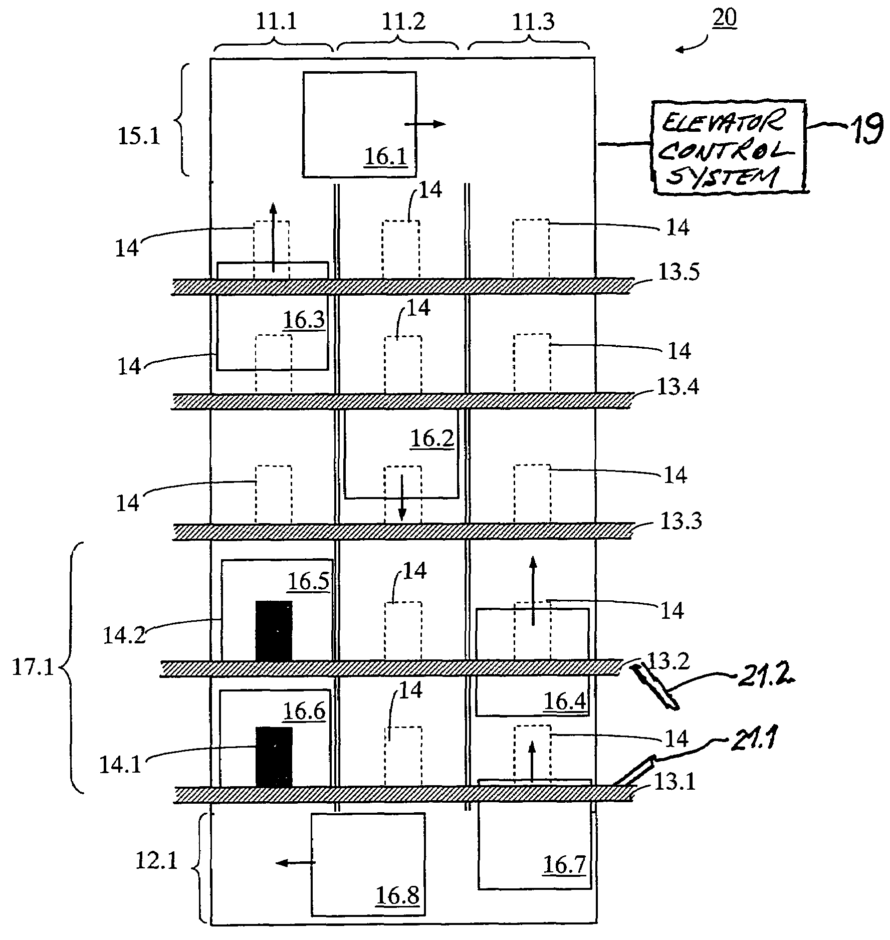
[0019]the present invention is described by reference to FIG. 1. An elevator installation 20 is shown in cross section from one side. The elevator installation 20 comprises at least one vertical elevator hoistway 11.1. In the embodiment of the present invention shown, there are n=3 vertical elevator hoistways 11.1, 11.2, and 11.3 arranged adjacent to each other. The vertical elevator hoistways 11.1, 11.2, and 11.3 can, but need not, be spatially separated from each other. A total of five floors 13.1 through 13.5 are served. In the elevator hoistways 11.1, 11.2, and 11.3 are several individually movable elevator cars 16.1 through 16.8. In the example shown, there is at least one transfer zone 12.1 in the area beneath a boarding zone 17.1 which allows movement of the elevator cars 16.1 through 16.8 between the elevator hoistways 11.1, 11.2, and 11.3. The boarding zone 17.1 in the present exemplary embodiment is regarded as comprising the entrance areas of the two lowest floors 13.1, 1...

second embodiment

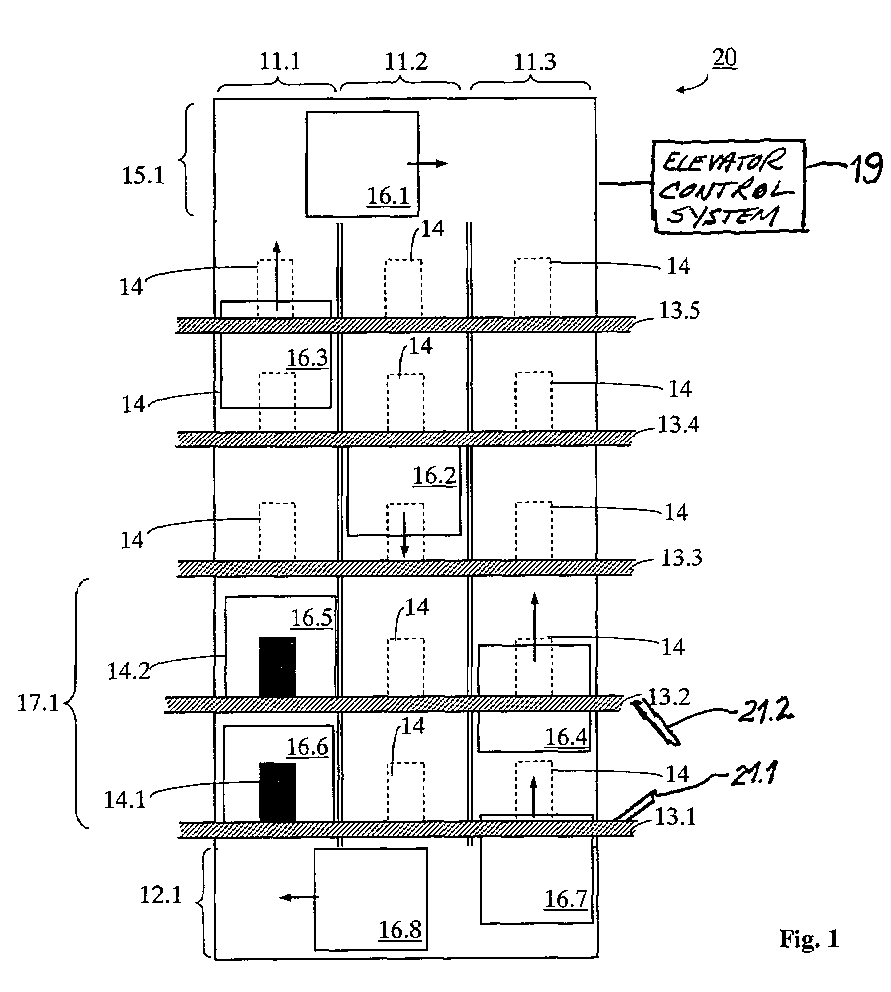
[0040]The arrangement and an alternate mode of operation of a second embodiment elevator installation 20a according to the present invention is represented in FIG. 2, only the fundamental elements being shown. The elevator installation 20 shown has n=3 elevator hoistways 11.1, 11.2, and 11.3. Here, too, the five floors 13.1 through 13.5 are served. Within the elevator hoistways 11.1 through 11.3 there are several individually movable elevator cars 16.1 through 16.6 which are currently deployed. An elevator car 16.7 is currently not moving and therefore blocks the elevator hoistway 11.3 (marked with a “No vehicles” symbol 18). A transfer zone 12.1 is provided in the area of the lower boarding zone 17.1 and a transfer zone 15.1 is provided in the vicinity of the upper end of the hoistway which allows movement of the elevator cars 16.1 through 16.7 between the elevator hoistways 11.1 through 11.3.

[0041]The advantages of the present invention are described by reference to an (exceptiona...

third embodiment

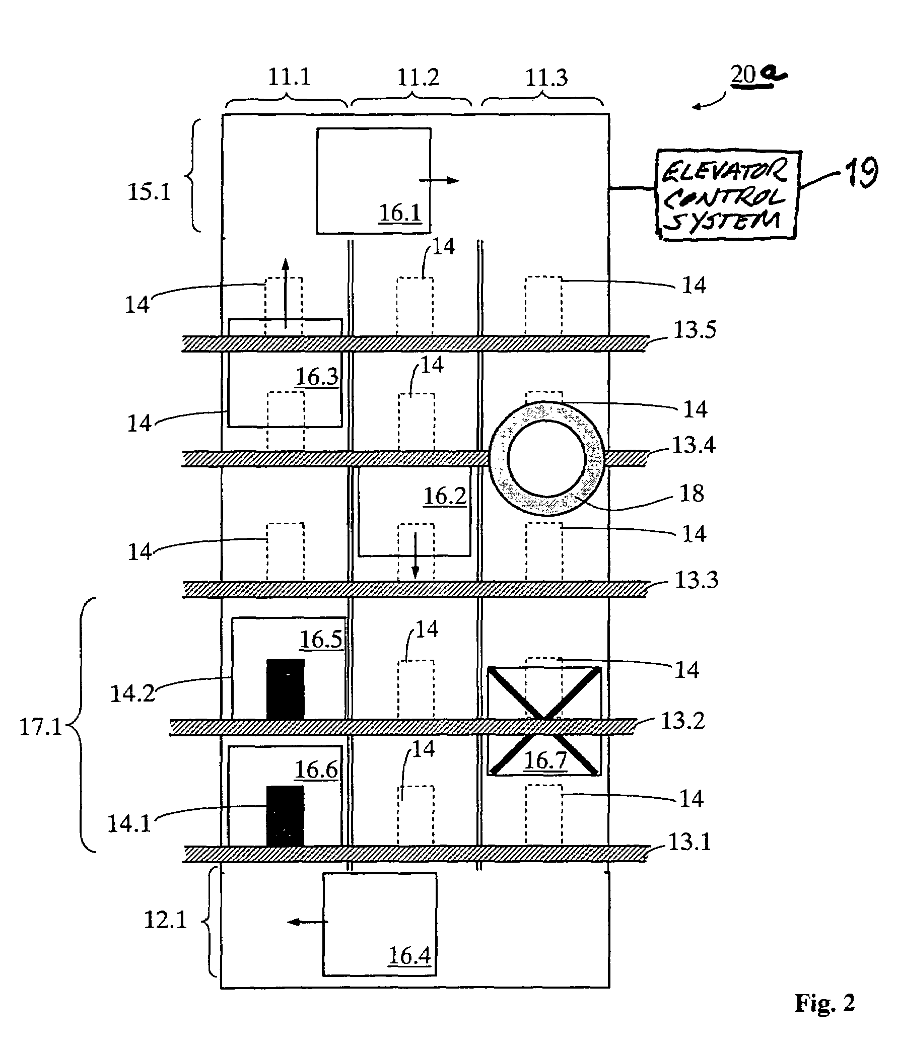
[0043]A further, similar third embodiment is explained by reference to FIG. 3, but this figure will only be discussed here to the extent that it differs from the previous figures. An elevator installation 20b has three elevator hoistways 11.1 through 11.3. Arranged under the floor 13.1 are two transfer zones 12.1 and 12.2. A further transfer zone 15.1 is situated at the upper end of the hoistway. The elevator hoistway 11.3 is again blocked (marked with the “No vehicles” symbol 18). Two elevator cars 16.5 and 16.6 are ready for loading / unloading. Two further elevator cars 16.4 and 16.8 are moving horizontally under the elevator hoistway 11.1 so as to be able to move up as quickly as possible after the elevator cars 16.5, 16.6 have departed upward either individually or in double-deck arrangement. With this embodiment, the two elevator cars 16.4 and 16.8 can already be brought into a moving-up position so as to accelerate moving up. The transfer zones 12.1, 12.2 are preferably so desi...


PUM


Abstract

An elevator installation has a vertical elevator hoistway and a plurality of elevator cars individually movable therein. An elevator control system readies at least two of the elevator cars in the hoistway in an area of two mutually adjacent entrance areas. Thus, simultaneous loading / unloading of the elevator cars via the entrance areas is possible. The two elevator cars then travel to destination floors, the first elevator car traveling a distance which is at least as great as that traveled by the second elevator car.

Description

BACKGROUND OF THE INVENTION[0001]The present invention relates to elevator installations with a plurality of individually movable elevator cars and a method of operating such elevator cars.[0002]Every elevator installation occupies a certain proportion of the space in a building which depends on the amount of traffic. The greater the amount of traffic, and the higher the building, the more space the elevator installation needs in relation to the usable surface area (net usable surface area) of the building. The performance of an elevator installation can be expressed as its so-called handling capacity. The handling capacity indicates how many persons can be transported per minute in an office building when the amount of traffic is high, for example at the start of a working day.[0003]It is of great interest to minimize the space required by an elevator installation.[0004]There are various methods of readying and operating more than only one elevator car in one elevator hoistway, of ...

Claims


Application Information

Patent Timeline
Patent Type & Authority Patents(United States)
IPC IPC(8): B66B1/20B66B9/00
CPCB66B1/2466B66B1/2491B66B9/00B66B9/003B66B2201/103B66B2201/307B66B2201/402B66B2201/403Y10S187/902
Inventor DUENSER, THOMASANGST, PHILIPP
Owner INVENTIO AG
Why Eureka
Try Eureka