End connector for barrier devices

a technology of end connectors and barriers, applied in roadway safety arrangements, roads, construction, etc., can solve the problems of high friction factor, little or no ability of concrete barriers to absorb shock upon impact, and heavy weight of reinforced concr

Inactive Publication Date: 2009-05-26
TRINITY HIGHWAY PROD LLC
View PDF44 Cites 25 Cited by
  • Summary
  • Abstract
  • Description
  • Claims
  • Application Information

AI Technical Summary

Benefits of technology

[0010]The second coupling element on the opposite end wall of each barrier device includes a neck section protruding outwardly from a concave pivot surface formed on such opposite end wall between the top and bottom walls of the barrier device. The neck section is connected to a cylindrical-shaped pivot pin. In forming a barrier wall with the barrier devices of this invention, the pivot pin of the second coupling element of one barrier device is inserted into the inner cavity of the first coupling element of an adjacent barrier. The pivot pin is captured within the inner cavity, and the neck portion of the second coupling element extends between the two arms of the first coupling element. Because the two arms of the first coupling element are spaced about 45° apart, the barrier with the second coupling element can pivot throughout essentially the same 45° angle relative to the adjacent barrier, e.g. approximately 22.5° in both the clockwise and counterclockwise direction. This permits a barrier wall to be formed having a substantial curve, compared to that permitted in prior barrier device designs, allowing the barrier devices herein to be used on most curved roadways and similar applications.

Problems solved by technology

One problem with the Jersey-style highway barriers described above is the weight of reinforced concrete.
Additionally, concrete barriers have little or no ability to absorb shock upon impact, and have a high friction factor.
This increases the damage to vehicles which collide with such barriers, and can lead to serious injuries to passengers of the vehicle.
One problem with barrier devices of the type described above is that the coupling elements which connect one barrier device to an adjacent one permit limited pivotal movement.
While a gradual curve along a barrier wall formed by a number of interconnected barrier devices may be obtained, the amount of articulation between adjacent barriers is limited to a few degrees.
Consequently, such barrier devices may not be used on roadways or other applications with sharper curves.

Method used


Image

  • End connector for barrier devices
  • End connector for barrier devices
  • End connector for barrier devices

Examples


Embodiment Construction

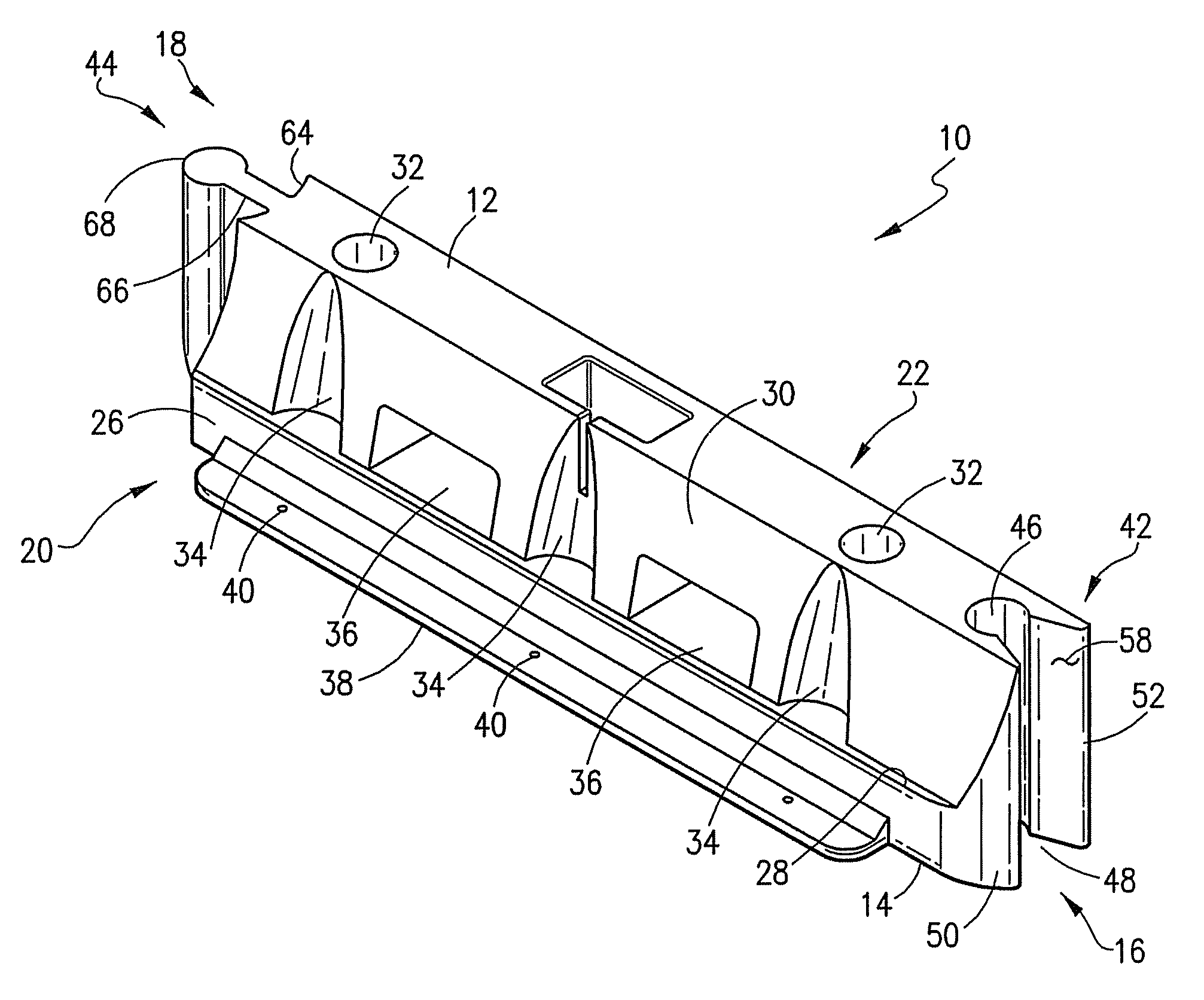
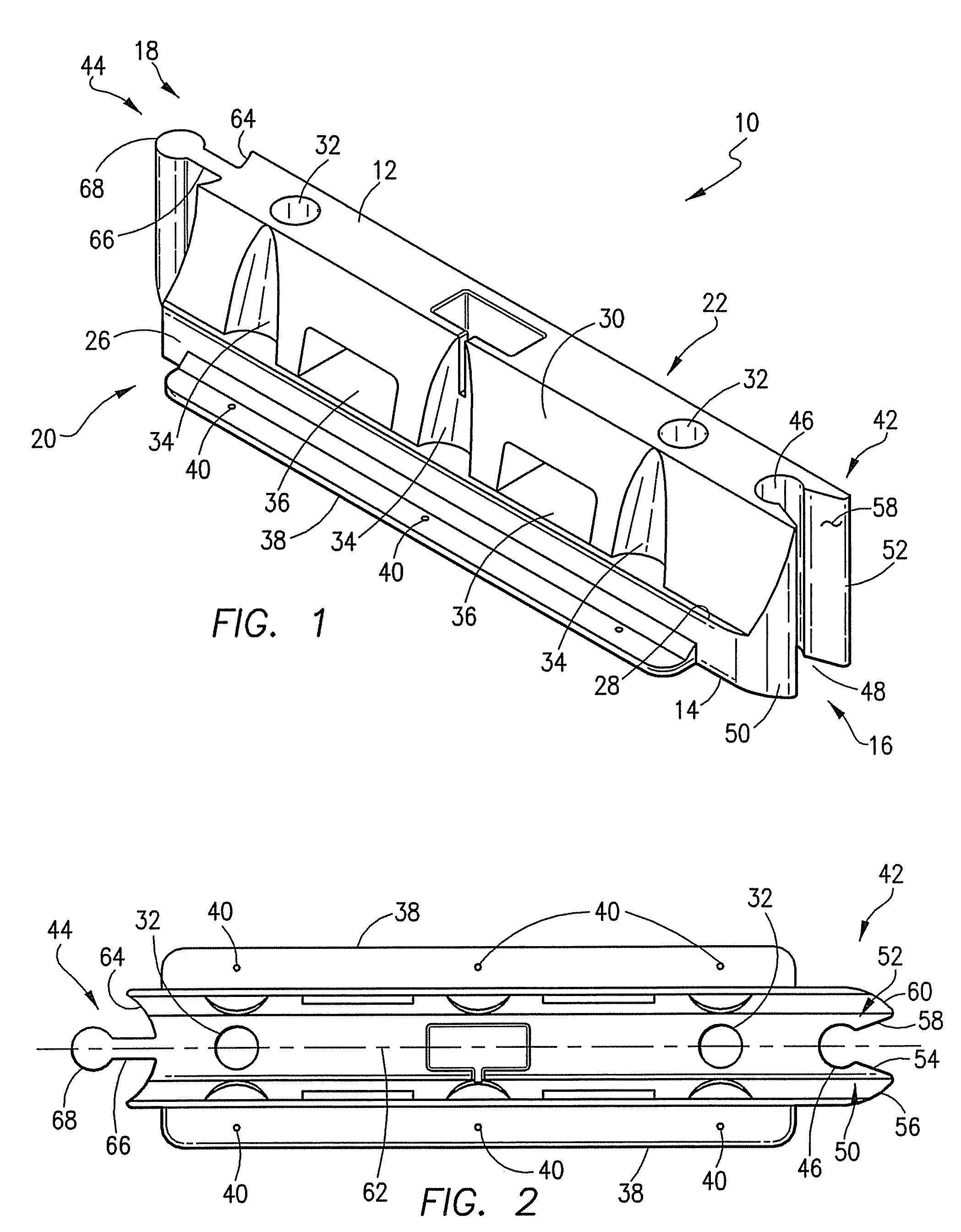
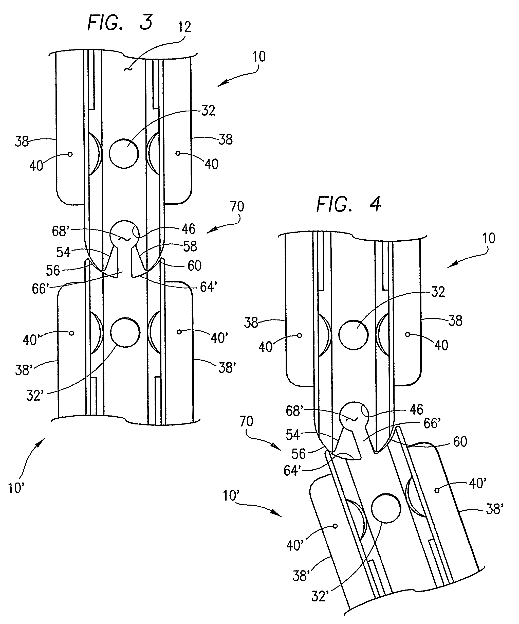
[0016]Referring now to the Figs., the barrier device 10 of this invention comprises a top wall 12, a bottom wall 14, opposed end walls 16, 18, and, opposed side walls 20, 22 which are interconnected to collectively define a hollow interior. A number of barrier devices 10 may be arranged end-to-end to form an essentially continuous wall. Two barrier devices 10, 10′ are shown in FIGS. 3 and 4 which are identical in structure and function, and therefore the same reference numbers are used to identify like structures with the addition of a “′” to the numbers associated with the barrier 10′.

[0017]In the presently preferred embodiment, each of the walls 12-22 are formed of a semi-rigid plastic material chosen from the group consisting of low density polyethylene, acrylonitrile or butadiene styrene, high impact styrene, polycarbonates and the like. These plastic materials are all inherently tough and exhibit good energy absorption characteristics. They will also deform and elongate, but wi...


PUM


Abstract

An end connector for a barrier device is provided which permits articulation of one barrier device through a relatively large angle with respect to an adjacent barrier device, so that a barrier wall may be formed of a plurality of barrier devices connected end-to-end having a significantly curved shape.

Description

FIELD OF THE INVENTION[0001]This invention relates to barrier devices for vehicular traffic control, soil erosion containment, impact attenuation and the like which can be interconnected with one another to define a barrier wall structure, and, more particularly, to an end connector for barrier devices which allows them to articulate relative to one another through an angle of about 22.5° in both the clockwise and counterclockwise directions when arranged in an interconnected line forming a barrier wall.BACKGROUND OF THE INVENTION[0002]A variety of different devices have been developed for absorbing the kinetic energy resulting from impact with a moving vehicle, and for the containment of forces exerted by soil or water. Highway barriers and channelizers, for example, are intended to provide a continuous wall or barrier along the center line or shoulder of a highway when laid end-to-end to absorb grazing blows from moving vehicles. One commonly used highway barrier is formed of pre-...

Claims


Application Information

Patent Timeline
Patent Type & Authority Patents(United States)
IPC IPC(8): E01F13/02
CPCE01F15/083E01F15/086E01F15/088
Inventor YODOCK, JR., LEO J.YODOCK, III, LEO J.YODOCK, GUY C.
Owner TRINITY HIGHWAY PROD LLC
Why Eureka
Try Eureka