Column-beam connection structure

A joint, column-beam technology, applied in welding equipment, building structure, application, etc., can solve the problems of poor joint efficiency, insufficient joint, and prone to welding.

Inactive Publication Date: 2011-10-05
ARCREATE
View PDF6 Cites 2 Cited by
  • Summary
  • Abstract
  • Description
  • Claims
  • Application Information

AI Technical Summary

Problems solved by technology

Therefore, when the length in the beam axis direction of the cover plate also serving as the backing plate is 100 to 150 mm, which is several times the length in the beam axis direction of the conventional backing plate, the web height of 300 mm or more is insufficient.
[0019] In addition, in Patent Document 2, the joint of the flange side of the cover plate is a fillet weld, and since the maximum force in the beam axis direction can only be expected to be 1 / √3 of the thickness of the weld seam, that is, the thickness of the cover plate, the joining efficiency is poor.
[0020] In addition, in Patent Document 2, since the cover plate is spliced ​​with the beam flange, there is no gap between the cover plate and the beam flange, and it is difficult to penetrate through the welding of the column side of the cover plate and the fillet welding of the beam flange side, and the welding gas at the root Poor drainage, prone to welding defects

Method used


Image

  • Column-beam connection structure
  • Column-beam connection structure
  • Column-beam connection structure

Examples


Embodiment Construction

[0082] Embodiments of the present invention will be described below.

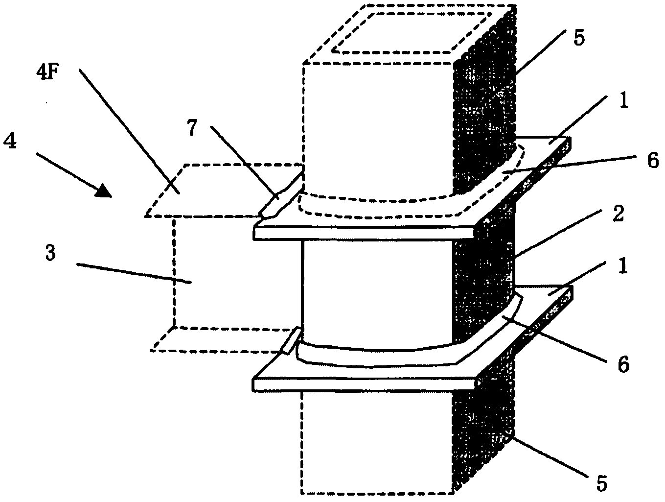
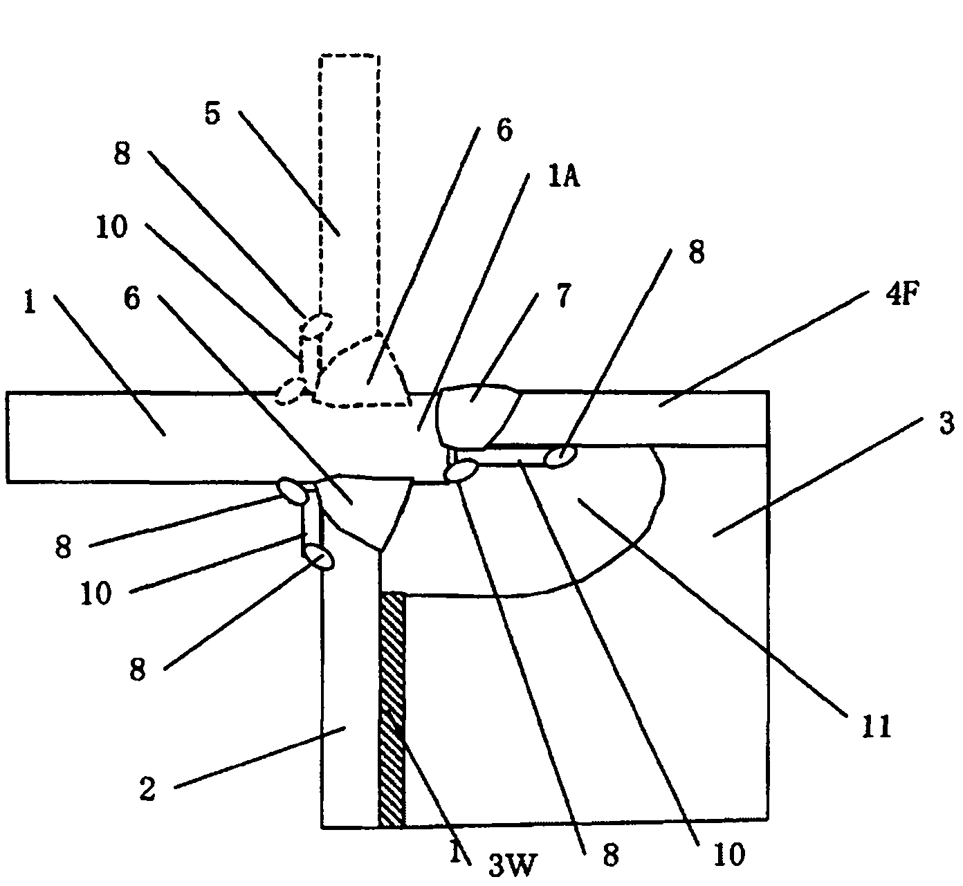
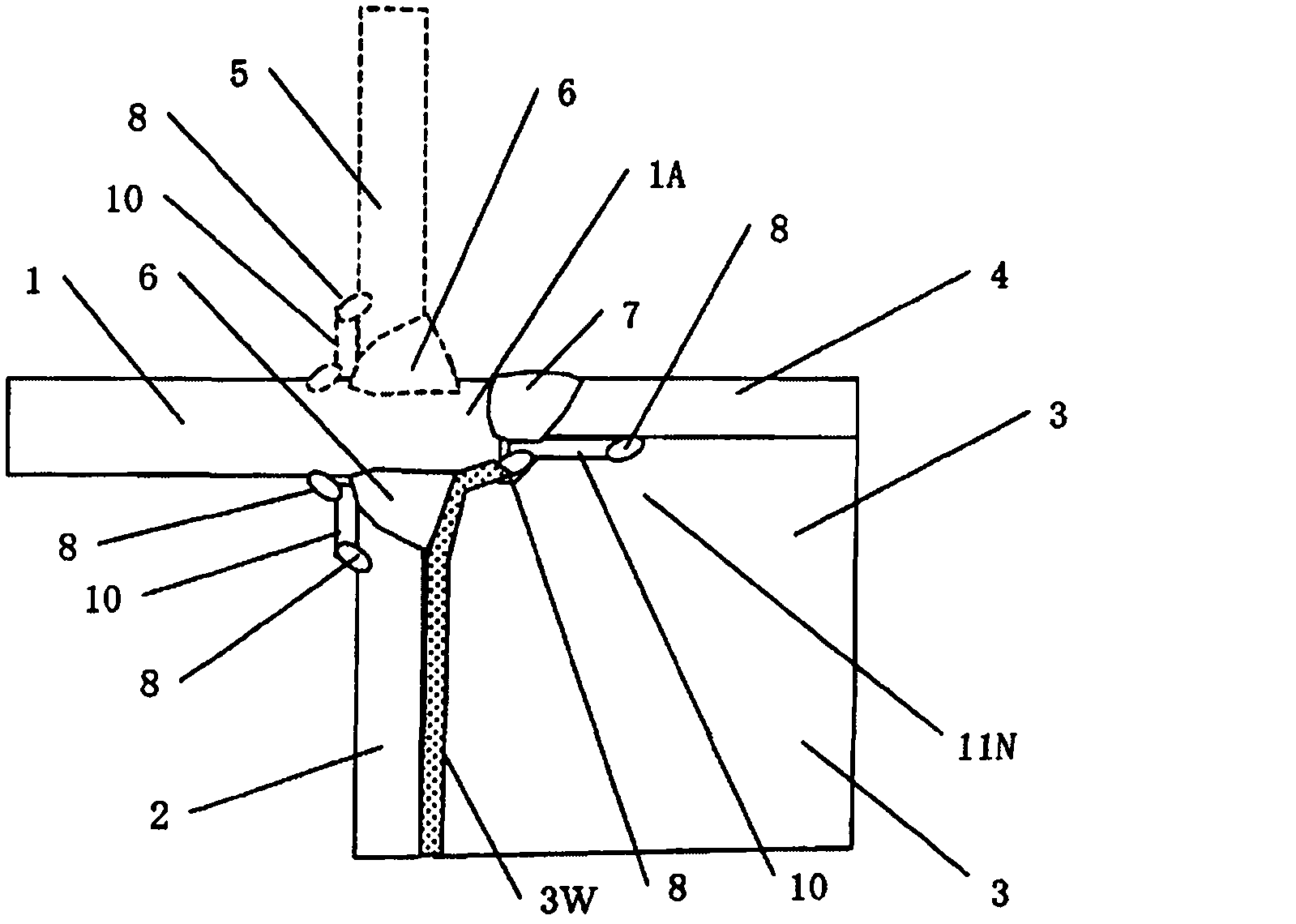
[0083] Figure 5 As an example of the embodiment of the present invention described in claim 1, in the building steel frame column-beam junction, the protrusion of the partition plate 1 from the column 5 is removed, and the thickness 1t of the partition plate 1 is increased, and the column shaft 5 A partition plate that overlaps and joins the welded portion of the partition plate 1 and the beam flange 4F and the welded portion 7 of the partition plate 1, and increases the plate thickness by 5 mm or more from the plate thickness of the beam flange on the side of the beam, preferably by adding a steel plate backing plate to the beam flange. At least this thickened portion of 1 is welded to the web. in addition, Figure 5 The structure of the column-beam joint is shown as follows. The structure of the column-beam joint is characterized in that a quadrilateral steel plate backing plate 10RP is closely attache...


PUM


Abstract

Bending moment applied to a beam causes out-of-plane deformation to a panel when the panel zone is hollow, and thereby a load bearing by a web cannot be expected in an elastic region. Since the section modulus of a beam end is limited to the section modulus of only the flange not including the web, the beam end has a low strength. Therefore, a beam larger in size which bears bending moment on the entire section of the beam must be used and an extra beam depth is required, thus causing an increase in the weight of a steel beam. As the result of various studies, it has been found that various problems could be resolved by increasing the plate thickness of a diaphragm, applying a backing plate to the top surface or the bottom surface of a beam flange, increasing the strength of the material of the beam flange, increasing the thickness of the diaphragm or the backing plate, notching a web, or hot working the bottom surface of the beam to impart prestress thereto.

Description

technical field [0001] The present invention relates to the structure of the column-beam joint, which, in the steel structure, will be unable or insufficient to share the bending moment applied to the beam web due to the cavity or arc-shaped gap in the plate area, The beam ends are strengthened by compensating for the strengthening of the beam end flanges, thereby reducing the beam height. Background technique [0002] In the case of the column-beam joint structure of the building steel frame structure using the penetrating diaphragm form of the rectangular section column, such as figure 1 As shown, it consists of a column 5, a beam 4, a plate 2, and a partition 1 passing through the column 5 and the plate 2. The beam flange 4F is welded 7 to the partition 1 protruding from the column 5, and the beam web 3 is welded 3W to the plate 2. There is also a form of this separator, that is, an inner separator form using a separator inserted into the column instead of a column penet...

Claims


Application Information

Patent Timeline
Patent Type & Authority Applications(China)
IPC IPC(8): E04B1/24B23K9/00
CPCE04B2001/2457E04B1/2403E04B2001/2454E04B2001/2415B23K31/12B23K9/0026B23K2201/04E04B2001/2445E04B2001/2448B23K2101/04
Inventor 内田昌克岩乡俊二岩乡速雄
Owner ARCREATE
Why Eureka
Try Eureka