RF phase modulation technique for performing acousto-optic intensity modulation of an optical wavefront

a phase modulation and wavefront technology, applied in non-linear optics, instruments, optics, etc., can solve the problems of affecting the resolution of the focused spot, and requiring additional and/or more expensive power supplies

Inactive Publication Date: 2009-05-26
HARRIS CORP
View PDF16 Cites 42 Cited by
  • Summary
  • Abstract
  • Description
  • Claims
  • Application Information

AI Technical Summary

Problems solved by technology

Conventional acousto-optic devices typically rely on the use of large and costly hybrid output radio frequency (RF) amplifiers to provide the requisite drive power necessary for use in operation of the device.
This results in the use of additional and / or more costly power supplies to meet both the integrated circuit (IC) and radio frequency amplifier requirements.
The combination of different coefficient-of-thermal expansion (CTE) for the platelet and optical medium, coupled by the low compliance interface, may lead to stress causing localized shear CTE expansion mismatch induced fracture and failure of large platelet acousto-optic devices subjected to extended temperature conditions.
These thermal transients can negatively impact the resolution of the focused spot, which can be produced.

Method used


Image

  • RF phase modulation technique for performing acousto-optic intensity modulation of an optical wavefront
  • RF phase modulation technique for performing acousto-optic intensity modulation of an optical wavefront
  • RF phase modulation technique for performing acousto-optic intensity modulation of an optical wavefront

Examples


Embodiment Construction

[0027]Different embodiments will now be described more fully hereinafter with reference to the accompanying drawings, in which preferred embodiments are shown. Many different forms can be set forth and described embodiments should not be construed as limited to the embodiments set forth herein. Rather, these embodiments are provided so that this disclosure will be thorough and complete, and will fully convey the scope to those skilled in the art. Like numbers refer to like elements throughout.

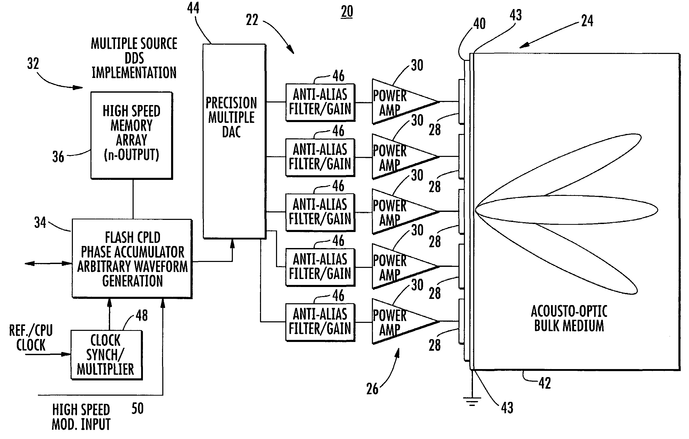
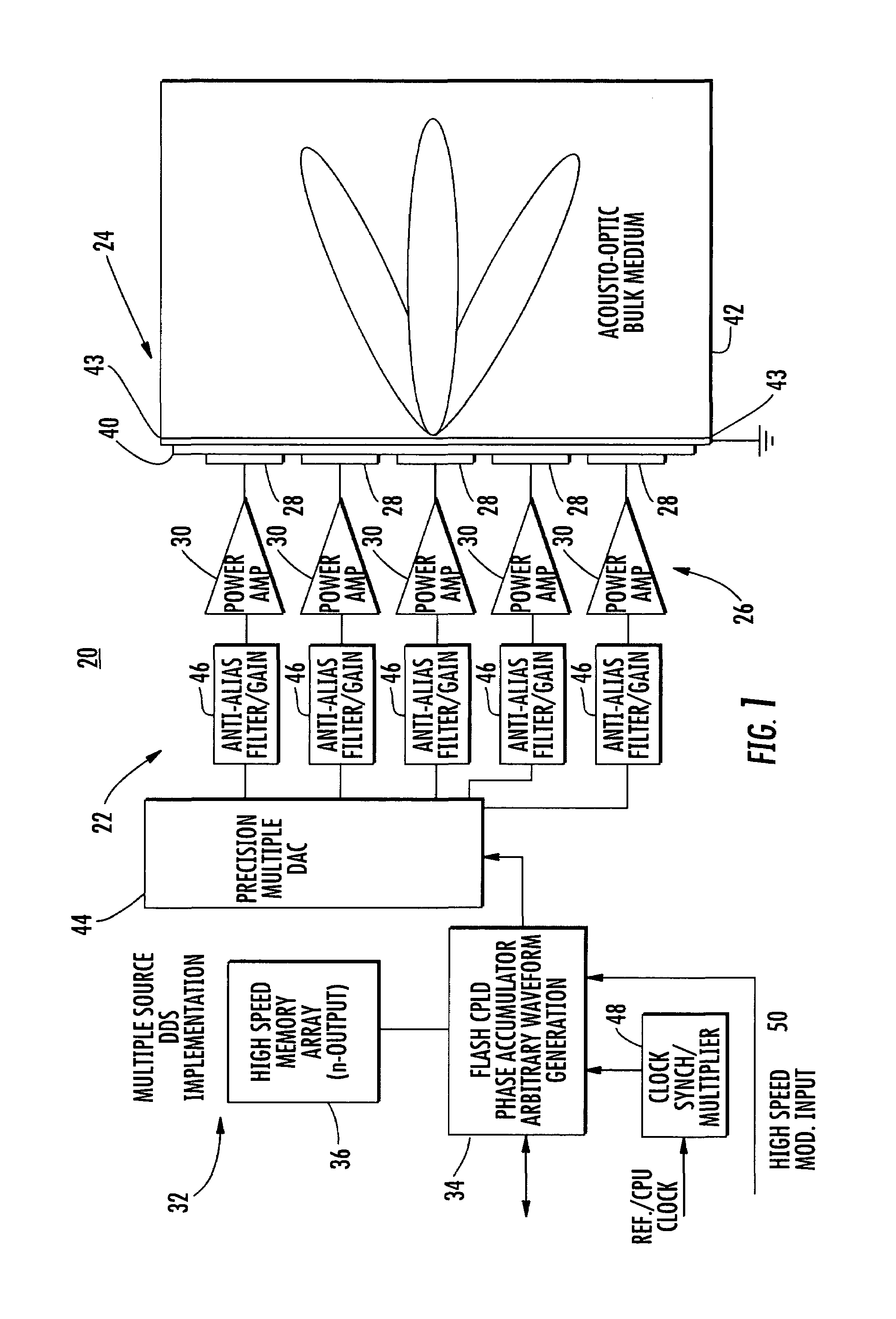
[0028]FIG. 1 is a block diagram of an acousto-optic modulator 20 and showing a transducer driver 22 for an acousto-optic device 24 as an acousto-optic modulator in accordance with a non-limiting example of the present invention. The acousto-optic modulator 20 shown in FIG. 1 overcomes the disadvantages of conventional acousto-optic modulators that rely on large and costly hybrid output RF amplifiers to provide a requisite drive power necessary for useful operation of the device. In these prior ...


PUM

PropertyMeasurementUnit
thickaaaaaaaaaa
acoustic thicknessaaaaaaaaaa

Abstract

An acousto-optic modulator includes an acousto-optic bulk medium and transducer attached to the acousto-optic bulk medium and formed as a linear array of electrodes. A transducer driver is connected to each electrode and is coherently phase driven to alter the angular momentum distribution of an acoustic field and alternately allow and inhibit phase matching between the optical and acoustic field and produce a desired intensity modulation of an optical wavefront.

Description

FIELD OF THE INVENTION[0001]The present invention relates generally to optical modulation systems and related components, and more particularly, to acousto-optical modulators and similar devices that modulate light beams using the acousto-optic effect.BACKGROUND OF THE INVENTION[0002]Acousto-optic modulators, sometimes referred to as Bragg cells, diffract and shift light using sound waves at radio frequency. These devices are often used for Q-switching, signal modulation in telecommunications systems, laser scanning and beam intensity control, frequency shifting, and wavelength filtering in spectroscopy systems. Many other applications lend themselves to using acousto-optic devices.[0003]In such acousto-optic devices, a piezoelectric transducer, sometimes also referred to as an RF transducer, is secured to an acousto-optic bulk medium as a transparent optical material, for example, fused silica, quartz or similar glass material. An electric RF signal oscillates and drives the transd...

Claims


Application Information

Patent Timeline
Patent Type & Authority Patents(United States)
IPC IPC(8): G02F1/11G02F1/01
CPCG02F1/113G02F1/332G02F2201/122G02F1/11G02F1/33
Inventor WASILOUSKY, PETER A.
Owner HARRIS CORP
Why Eureka
Try Eureka