
Analog layout module generator and method

a technology of analog layout and module generator, applied in the field of analog integrated circuit physical design, can solve the problems of large labor cost, time-consuming and labor-intensive physical design of integrated circuits, and the complexity of analog circuit layout, saving a great deal of labor

Active Publication Date: 2009-06-02
CADENCE DESIGN SYST INC
View PDF13 Cites 138 Cited by
  • Summary
  • Abstract
  • Description
  • Claims
  • Application Information

AI Technical Summary

Benefits of technology

The invention is a computer-based method and apparatus for designing integrated circuits. It allows users to select and display a layout of circuit devices on a computer screen, and then populate empty cells in the array with the selected devices. The method includes aligning and rotating the devices, and can also insert dummy rows or columns and connect them to an electrical distribution network. The invention simplifies the process of designing complex integrated circuits, making it easier for engineers to create and test new designs.

Problems solved by technology

Heretofore, the physical design of integrated circuits (ICs), especially Analog ICs, was a time-consuming and labor-intensive task.
The complexity of analog circuit layout comes from the extreme sensitivity of the continuous analog signal over the device interaction, fabrication process and operating environment, which require fine tuning of the physical circuit layout.
Physical circuit layout is not usually done from scratch, but instead using a hierarchical design library of scalable components and different types of “sub circuits,” thereby saving a great deal of labor.
Although the number of module types is usually limited in the analog design domain (for example, current mirror, differential pair, diode-connected transistor, etc.), the creation of technology-independent parameterized modules is very complicated and time-consuming.
The difficulty comes from the great number of variants of the modules' layout topology, connectivity, technology dependency, and device dimension.
The steep learning curve and low maintainability seriously limit the adoption of those tools in industry.

Method used


Image

  • Analog layout module generator and method
  • Analog layout module generator and method
  • Analog layout module generator and method

Examples


Embodiment Construction

[0045]The present invention will be described with reference to the accompanying figures where like reference numbers correspond to like elements.

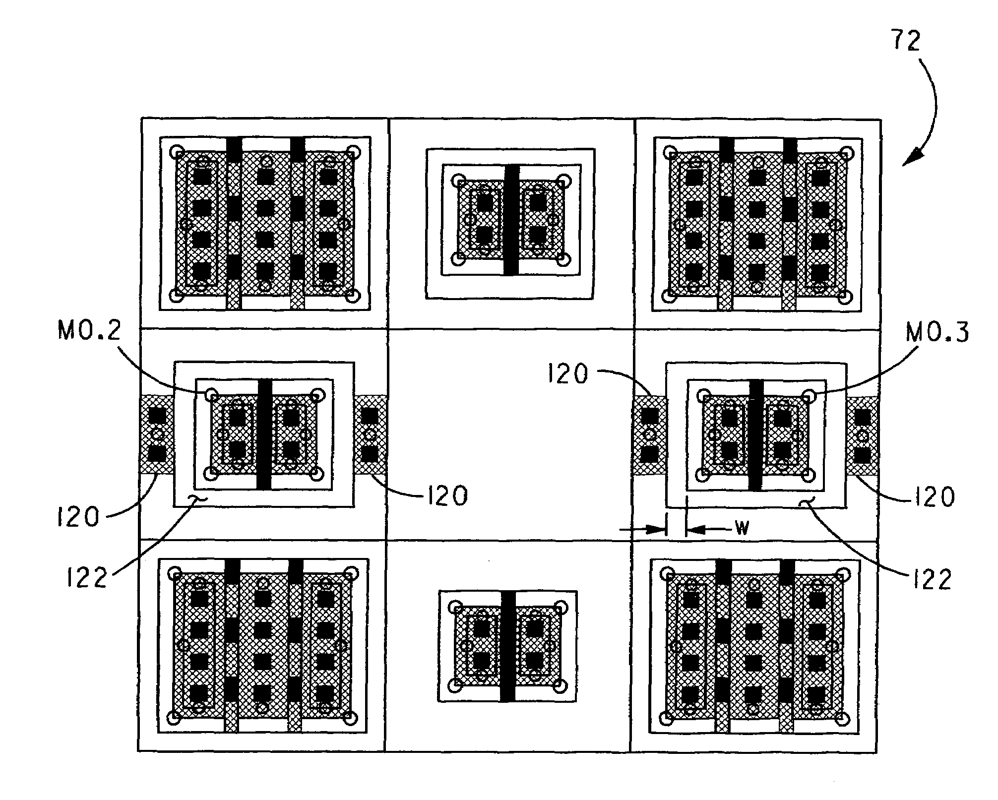
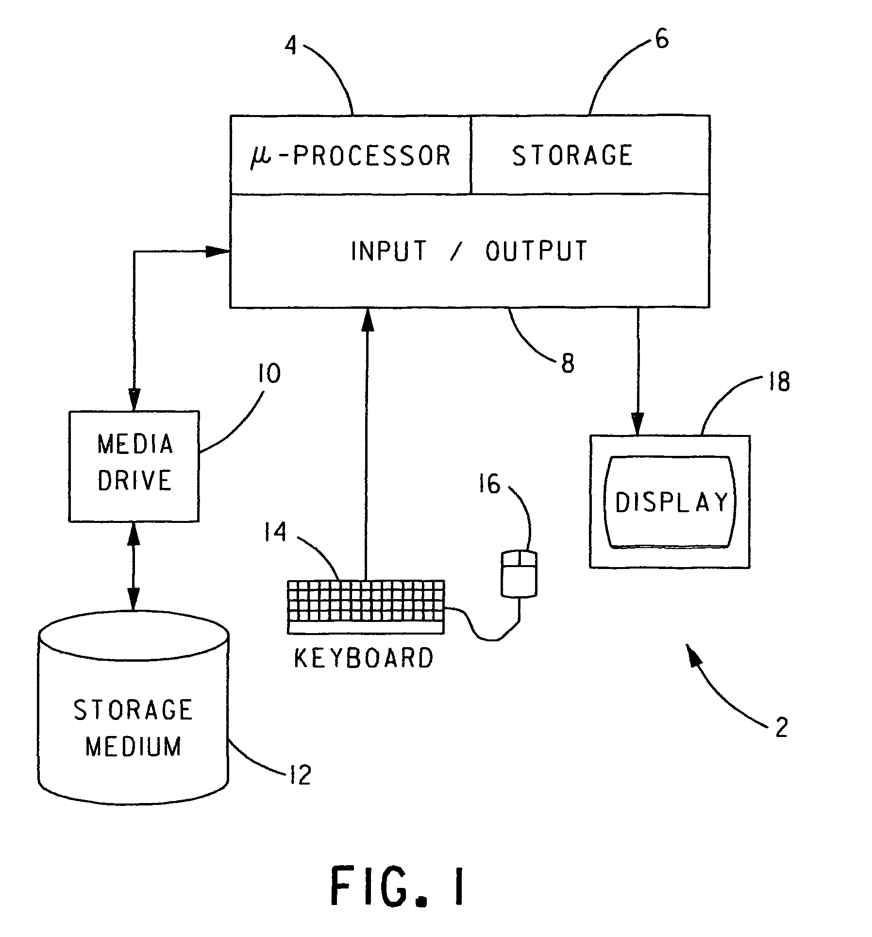
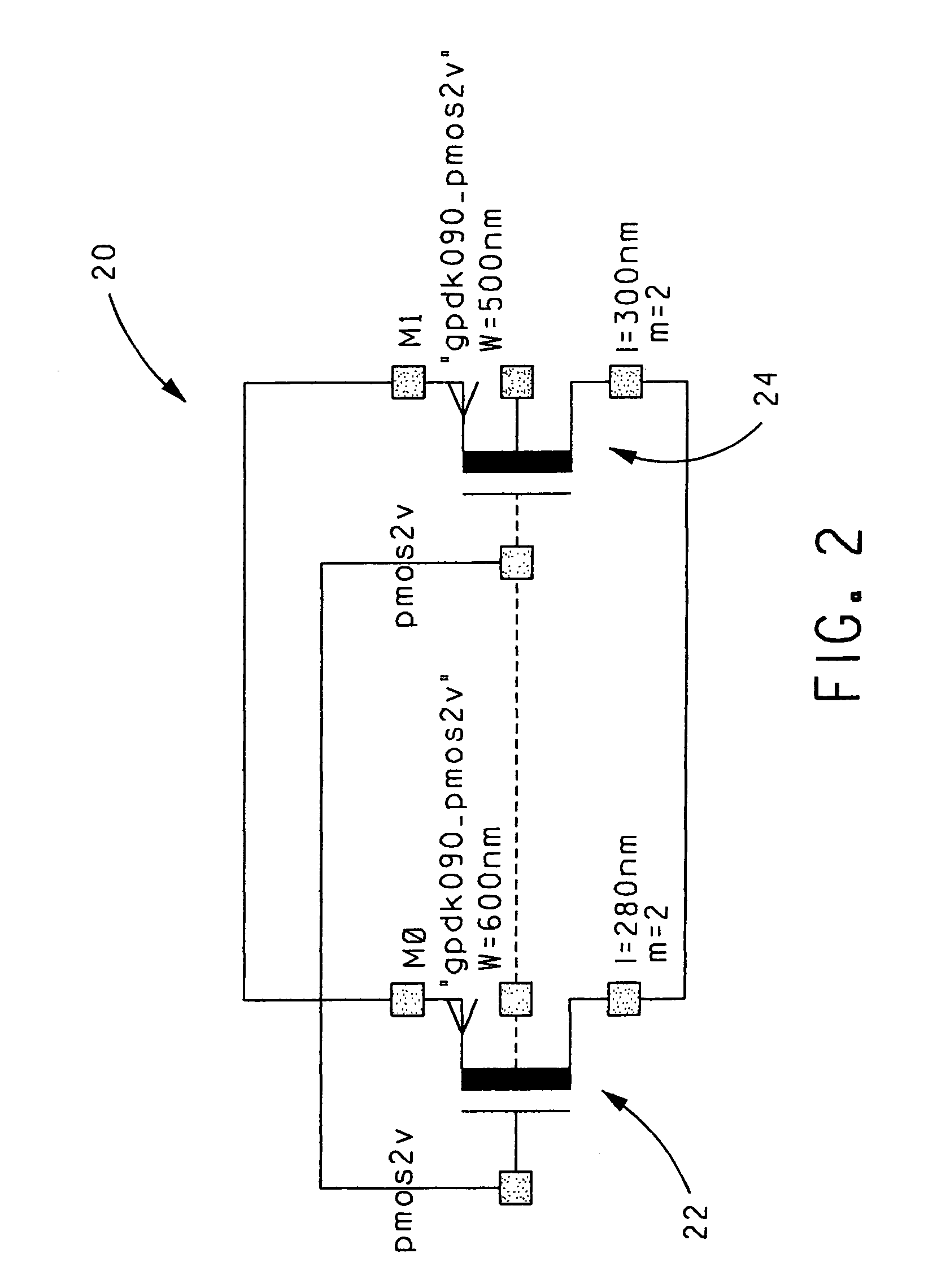
[0046]With reference to FIG. 1, the present invention is embodied in computer software which executes on one or more standalone or networked computers 2. Each computer 2 includes a microprocessor 4, a computer storage 6 and an input / output system 8. Each computer 2 can also include a media drive 10, such as a disk drive, CD ROM drive, and the like. Media drive 10 can operate with a computer readable storage medium 12 capable of storing the computer software that embodies the present invention, which computer software is able to configure and operate computer 2 in a manner to implement the present invention. Input / output system 8 can include a keyboard 14, a mouse 16 and / or a display 18. Computer 2 is exemplary of computers capable of executing the computer software of the present invention and is not to be construed as limiting the inventi...


PUM


Abstract

In a computer implemented method of device layout in an integrated circuit design an array having a plurality of cells is selected and stored in a memory of a computer. A schematic view of a plurality of interconnected circuit devices of a circuit is displayed on the computer's display. One or more of the circuit devices of the displayed schematic view are selected by a user. Responsive to the selection of each circuit device, a processing means of the computer populates an empty cell of the array in the memory of the computer with a corresponding layout instance of the circuit device, wherein each layout instance represents a physical arrangement of material(s) that form the corresponding selected circuit device.

Description

BACKGROUND OF THE INVENTION[0001]1. Field of the Invention[0002]The present invention relates to the physical design of integrated circuits, especially analog integrated circuits, and more particularly, to the improved automation of integrated circuit design.[0003]2. Description of Related Art[0004]Heretofore, the physical design of integrated circuits (ICs), especially Analog ICs, was a time-consuming and labor-intensive task. The complexity of analog circuit layout comes from the extreme sensitivity of the continuous analog signal over the device interaction, fabrication process and operating environment, which require fine tuning of the physical circuit layout. To minimize these degrading influences on IC performance, analog layout engineers adopt various geometrical techniques such as, without limitation: interdigitation, device merging, matching, symmetrical layout, guard ring protection, etc. How these techniques are applied to the layout is mostly dependent on the designer's ...

Claims


Application Information

Patent Timeline
Patent Type & Authority Patents(United States)
IPC IPC(8): G06F17/50
CPCG06F17/5063G06F17/5068G06F30/36G06F30/39
Inventor WANG, ZHIGANGFALLON, ELIASCOLWELL, REGIS R.
Owner CADENCE DESIGN SYST INC
Learn More