Adjustable scope mounting system

a technology of mounting system and adjustment mechanism, which is applied in the direction of sighting devices, weapons, weapon components, etc., can solve the problems of inability to easily reach the internal adjustment mechanism, inability to easily read the adjustment markings, and inability to accurately adjust the internal adjustment mechanism of most telescopic scopes. to achieve the effect of quick and reliabl

Active Publication Date: 2009-06-09
IVEY STEPHEN
View PDF27 Cites 81 Cited by
  • Summary
  • Abstract
  • Description
  • Claims
  • Application Information

AI Technical Summary

Benefits of technology

[0029]It is yet another object of the present invention to provide an adjustable mounting system for a telescopic scope having an elevation adjustment means adapted for making quick and reliable adjustment of coarse elevation from one elevation setting to another in low light or darkness.
[003...

Problems solved by technology

These internal adjustment mechanisms of most telescopic scopes are less accurate over the outer portion of their adjustment ranges.
The internal adjustment mechanisms frequently are positioned such that a shooter in the firing position cannot easily reach the internal adjustment mechanisms and cannot readily read the adjustment markings.
Additionally, the internal adjustment mechanisms of telescopic scopes may be inadvertently displaced by acceleration experienced during recoil and other shocks.
When hunting in rough terrain, obstacles may strike these exposed elevation adjusting dials and cause movement and misadjustment of the elevation adjustment set in the mounti...

Method used


Image

  • Adjustable scope mounting system
  • Adjustable scope mounting system
  • Adjustable scope mounting system

Examples


first embodiment

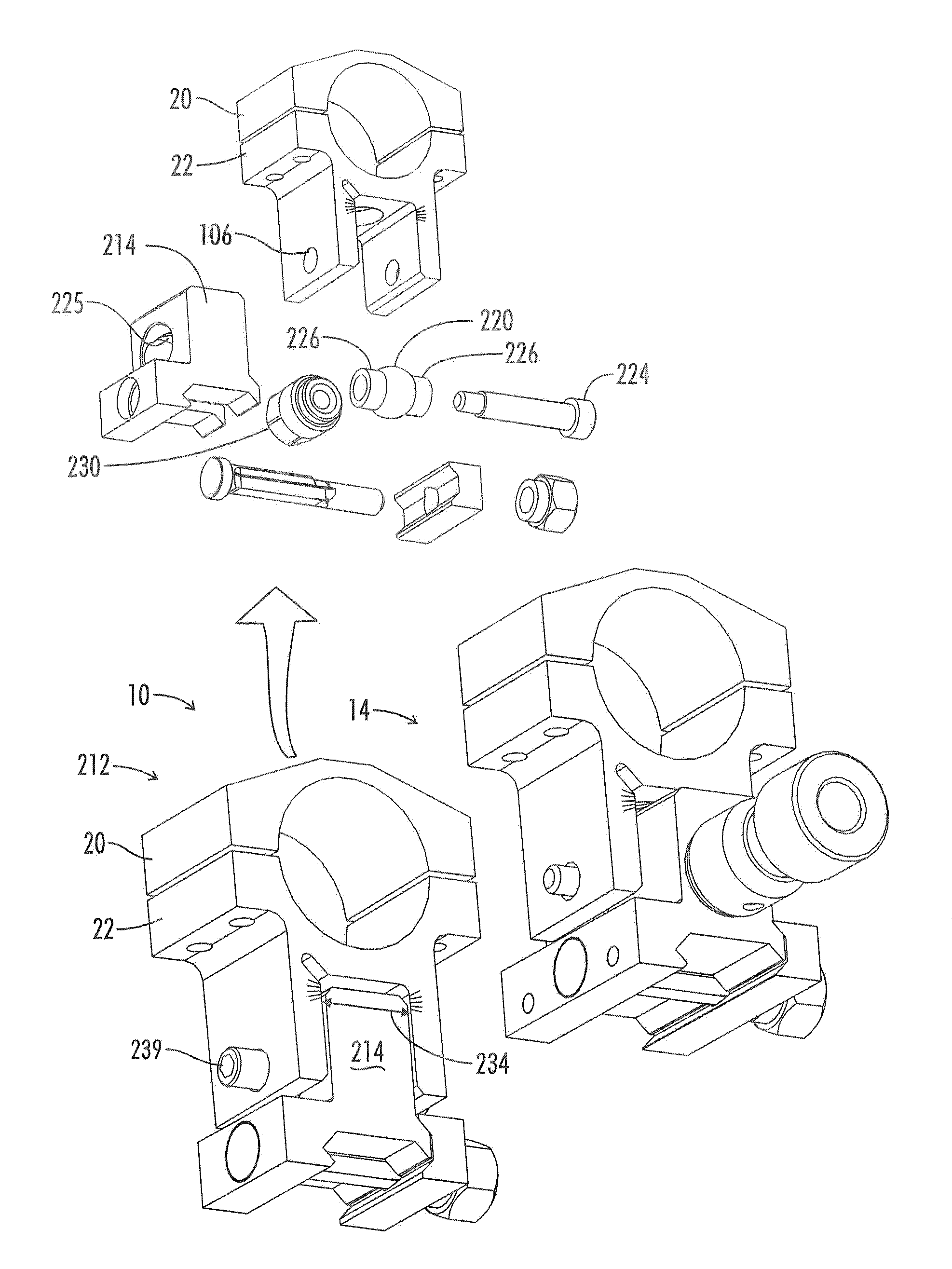
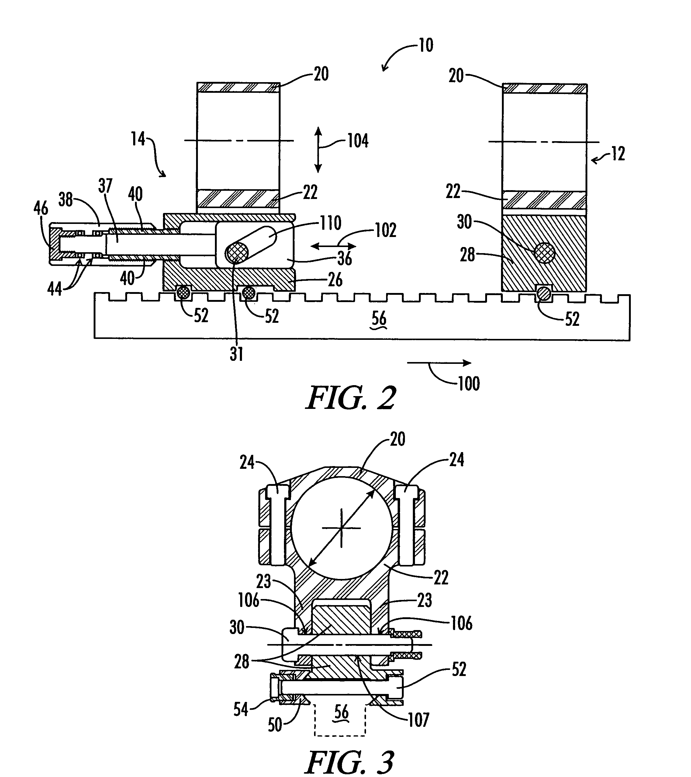
[0058]One preferred embodiment of the present invention is shown in FIGS. 2, 3 and 4. This embodiment of the mounting system 10 of the present invention is adjustable within 1.0 m.o.a. graduations between 0 m.o.a. and 150.0 m.o.a. This embodiment incorporates the scope rings and pivoting mount 12 of the Ivey 50 MOA mounting system, with the exception that a ratchet lever 32 is used to tighten or loosen the pivot pin 30. This modification allows for rapid, quiet tightening or loosening the pivot pin 30 without the use of external tools.

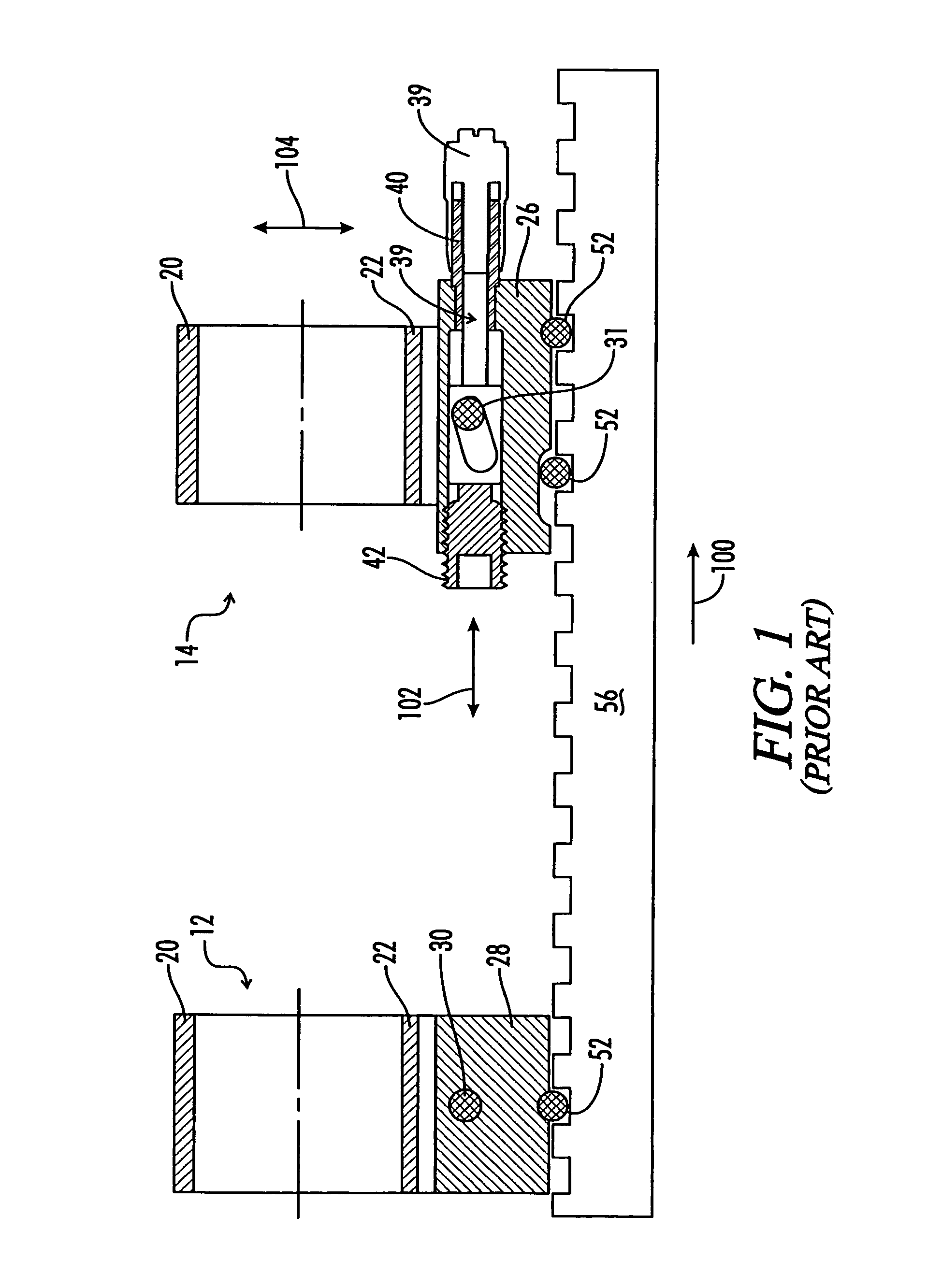
[0059]Referring to FIG. 2, the mounting system of the present invention includes a pivoting mount 12 located forward of the adjustable elevation mount 14 as indicated by the direction arrow 100. The elevation adjustment dial 38 is disposed in the rear portion of the adjustable elevation mount 14 and extends longitudinally further rearward. When in a shooting position, this configuration places the elevation adjustment dial adjacent to the shooter's eye...

second embodiment

[0064]Referring now to FIGS. 5 and 6, a second embodiment of the adjustable mounting system of the present invention is shown. The bi-directional elevation cam 36 has been modified to accept a floating angular-cut wedge plunger 58. A close fitting plunger bore is disposed in the elevation cam 36 such that the plunger bore penetrates into the angular slot 110. The wedge plunger 58 has a wedge face 70 with a slope approximating the slope of the angular slot 110. The wedge plunger 58 is disposed in the plunger bore and extends into the angular slot 110. Spring washers 60 backed by a setscrew 62 provide an axial bias that forces the wedge plunger 58 into continuous contact with the elevation pin 31. This axial bias of the wedge plunger 58 pushes the elevation pin 31 against the opposite wall of the angled slot 110 and provides for continuous capture of the elevation pin 31 by the elevation cam 36 at all points throughout the travel of the elevation cam 36 during elevation adjustments. T...

third embodiment

[0067]The adjustable mounting system of this invention is a novel improvement over the prior art in that the elevation cam is mechanically captured to a cam capture means so as to provide bi-directional control of elevation adjustments of the adjustable telescopic mounting system. The previously described embodiments provided a position dial as the cam capture means. However, in certain conditions, such as in covert military operations where there is low light or darkness, the elevation markings of the dial thimble may not be visible and use of an illumination device such as a flashlight or illuminated dial markings would be undesirable. Additionally, fine elevation adjustments contained within a sighting device held by the adjustable mounting system of the previously described embodiments are frequently sufficient to adjust between discrete coarse elevation settings of an adjustable elevation mount.

[0068]A third preferred embodiment of the adjustable mounting system of the present ...


PUM


Abstract

An adjustable mounting system for a telescopic scope includes an adjustable elevation mount formed from a scope ring and an adjustable sub-base. A clevis portion of the scope ring holds an elevation pin that is received by a vertical slot in the adjustable sub-base. An internally longitudinal bore is disposed though the adjustable sub-base and an externally threaded barrel disposed in an opening of the longitudinal bore. A cylindrical elevation cam having an angled slot is disposed in the longitudinal bore and includes a positioning rod that extends through a bore disposed through the barrel. The angled slot receives the elevation pin as it extends through the vertical slot of the adjustable sub-base. The angled slot may be smooth or stepped. A bi-directional cam capture means is mechanically coupled to the elevation cam and provides for longitudinal displacement of the elevation cam through the cam bore. Detent mechanisms are incorporated in the cam capture means to provide audible or felt indication of elevation position. In various embodiments the cam capture means may be: a rack and pinion device operated by dial handle; a plunger attached to the positioning rod and extending through the rear of the sub-base, a lever attached to the positioning rod and extending through a notched slot in the side of the sub-base, a position dial including a dial thimble affixed to the positioning rod and threadably engaged with a barrel disposed on the sub-base. Other embodiments include a windage gib adjustably positioned in a bore of a lower portion of the sub-base and adapted to laterally offset the sub-base from the firearm rail.

Description

CROSS-REFERENCES TO RELATED APPLICATIONS[0001]This application is a Continuation-In-Part application which claims benefit of co-pending U.S. patent application Ser. No. 11 / 032,705 filed Jan. 11, 2005 now U.S. Pat. No. 7,140,143, entitled “Adjustable Scope Mount” which is hereby incorporated by reference.BACKGROUND OF THE INVENTION[0002]The present invention relates generally to an apparatus and method of attaching and aligning an optical targeting or alignment system to a base. More particularly, this invention pertains to an apparatus and method of attaching and aligning optical sighting systems to a ballistic launcher. Even more particularly, this invention pertains to an adjustable mounting system for a telescopic scope.[0003]It is long known in the art to provide mechanical means for adjusting the elevation of sighting and ranging devices mounted to a base. Aiming or sighting devices, laser target illumination devices and laser ranging devices are commonly mounted to ballistic p...

Claims


Application Information

Patent Timeline
IPC IPC(8): F41G1/387
CPCF41G11/003
Inventor IVEY, STEPHEN
Owner IVEY STEPHEN
Why Eureka
Try Eureka