Generator assembly

a technology of generators and parts, applied in the direction of mechanical equipment, mechanical energy handling, machines/engines, etc., can solve the problems of increasing the size of the generator on the engine, hazard, and inconvenient passage of hot bleed pipes through the wings

Active Publication Date: 2009-06-09
ROLLS ROYCE PLC
View PDF12 Cites 45 Cited by
  • Summary
  • Abstract
  • Description
  • Claims
  • Application Information

AI Technical Summary

Benefits of technology

[0012]A non return valve may be provided in the inlet connection to prevent air passing out thereof. A non return valve may be provided between the inlet connection and the engine bleed valve or valves to prevent air travelling from the connection to the valve or valves.

Problems solved by technology

For future aircraft, and particularly those having composite wings, it is not desirable to have hot bleed pipes passing through the wings.
Especially with composite wings there would be a potential hazard in the event of a pipe failure.
This would however increase the size of the generators on the engine.
Such large generators could still be powered by the engine except that at descent conditions the electrical load will tend to slow the shaft and thus stall the compressor.
The descent idle speed of the engine could be increased to prevent such a stall, but this also increases the engine thrust during descent which is undesirable.
Not all airports though have the capability to start aircraft engines electrically, and particularly in view of the significant electrical power which may be required for this.
Not all aircraft engines can though be started pneumatically, and therefore the use of such aircraft has to be limited to locations where electrical starting is possible.

Method used


Image

  • Generator assembly
  • Generator assembly
  • Generator assembly

Examples


Embodiment Construction

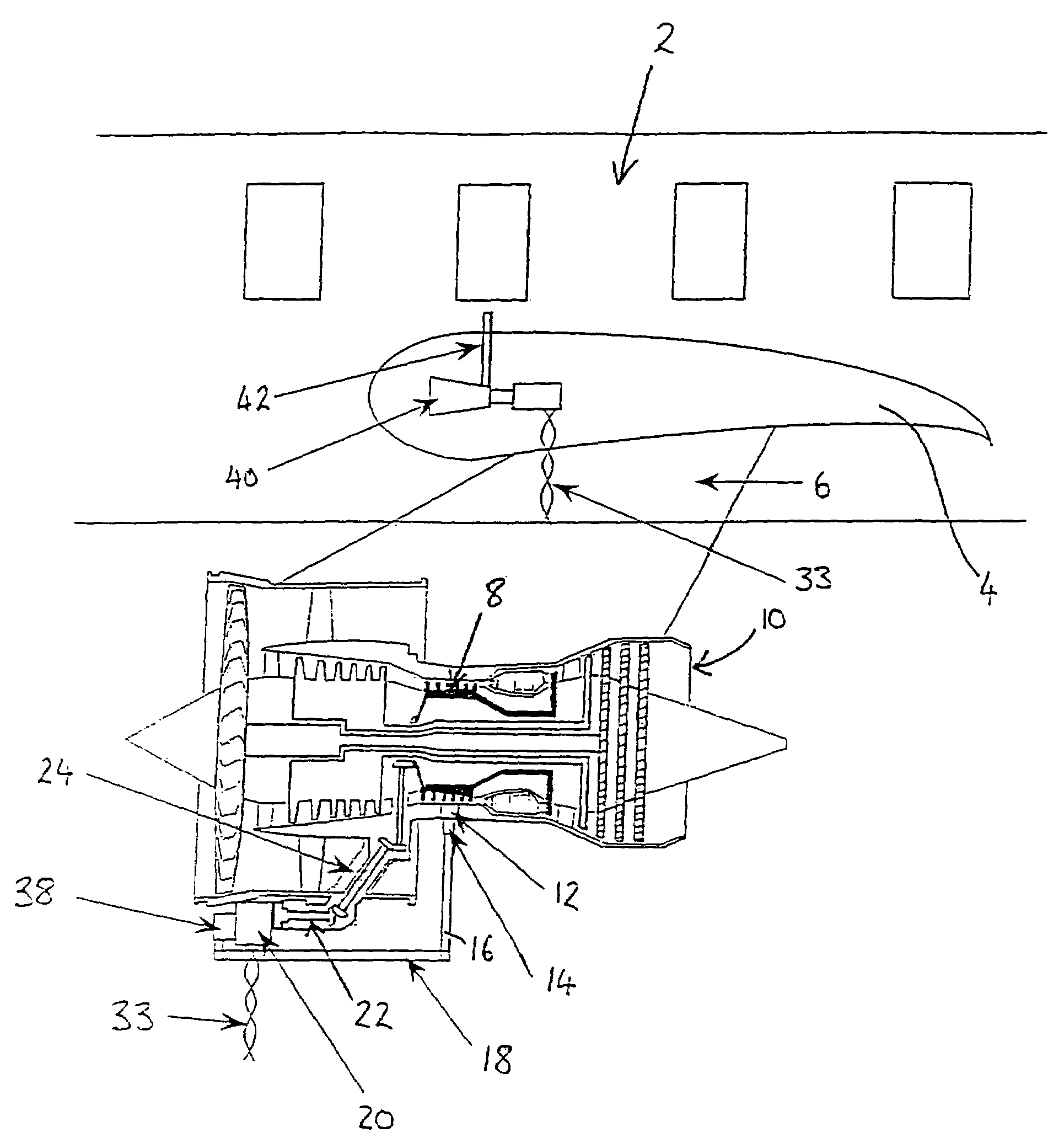
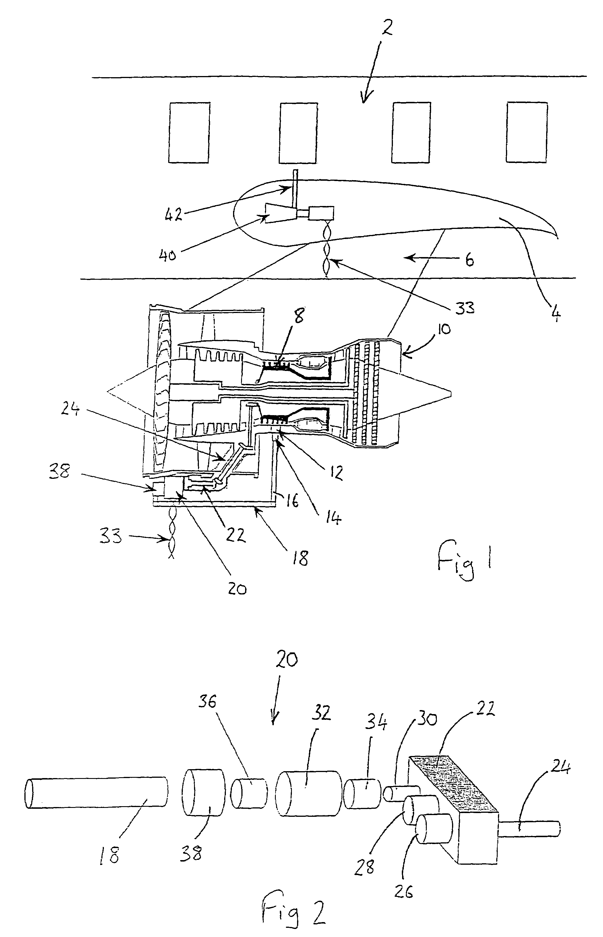
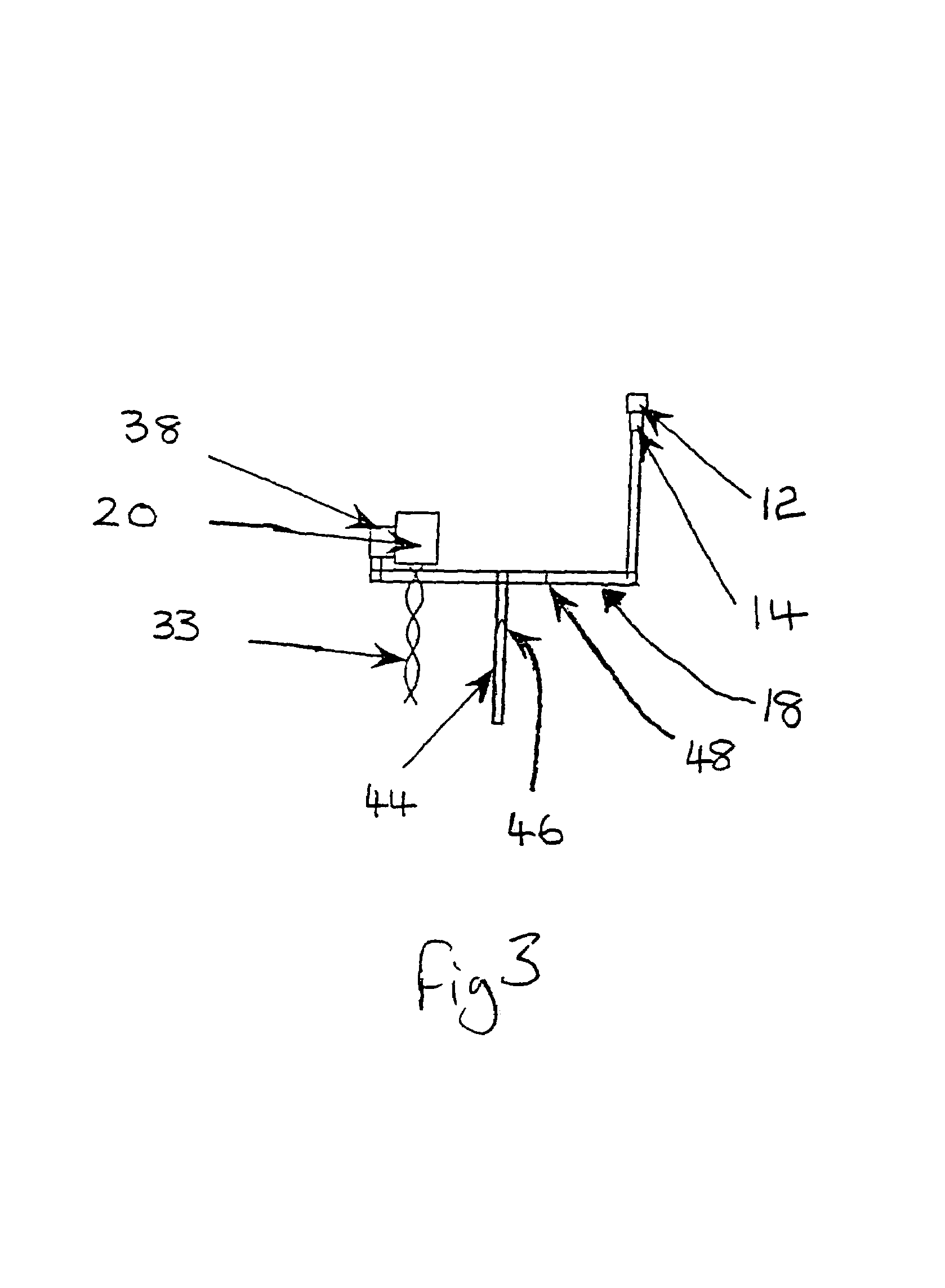
[0024]FIGS. 1 and 2 of the drawings show part of an aircraft 2 with a wing 4 and a pylon 6 which mounts a gas turbine engine 10. A plurality of selectively openable engine bleed valves 12 are provided for receiving air from the compressor 8 of the engine 10. The valves 12 connect to a manifold 14 which directs air from the valves 12 through an air pipe 16 leading to an air supply pipe 18.

[0025]The air supply pipe 18 connects to an electrical generator unit 20 which connects to an accessory gearbox 22. The gearbox 22 is driven by a shaft 24 which connects to the engine 10. The gearbox 22 includes connections 26, 28, 30 respectively to the starter motor, number one hydraulic pump and to the electrical generator unit 20.

[0026]The unit 20 includes an electrical generator 32 connected to the connection 30 by a first sprag clutch 34. The generator 32 has an electrical connection 33. The unit 20 also comprises a second sprag clutch 36 on an opposite end of the generator 32 from the clutch ...


PUM


Abstract

A generator assembly for a gas turbine engine. The assembly includes an electrical generator connected via a first sprag clutch to an accessory gearbox driven by the engine. The generator is also connected by a second sprag clutch to an air turbine connected to engine bleed valves which are selectively open when the engine speed falls below a predetermined level. The clutches are arranged such that the generator is driven at any time by the fastest rotating of the gearbox and turbine.

Description

FIELD OF INVENTION[0001]This invention concerns a generator assembly for a gas turbine engine, a gas turbine engine, an aircraft, a method of generating electricity from a gas turbine engine, and a method of providing cabin pressurisation in an aircraft.BACKGROUND OF THE INVENTION[0002]Currently electrical generators on large civil aircraft are driven by the accessory (external) gearbox. Also on such aircraft cabin pressurisation is generally provided by air bled from the engines. For future aircraft, and particularly those having composite wings, it is not desirable to have hot bleed pipes passing through the wings. Especially with composite wings there would be a potential hazard in the event of a pipe failure.[0003]As an alternative to the above outlined arrangement, cabin pressurisation can be achieved by having compressors onboard the aircraft and powering them by electricity generated by the engine. This would however increase the size of the generators on the engine. Such lar...

Claims


Application Information

Patent Timeline
Patent Type & Authority Patents(United States)
IPC IPC(8): F02C7/32F02C7/36H02K7/108
CPCF02C7/32H02K7/108F02C7/36
Inventor BUTT, DAVID CMAGUIRE, ALAN R
Owner ROLLS ROYCE PLC
Why Eureka
Try Eureka