
Self unloading pull-type trailer

a self-unloading, pull-type technology, applied in the direction of positive displacement liquid engine, applications, ways, etc., can solve the problem of limiting the options of the operator of any of these systems, and achieve the effect of allowing the operator more flexibility in selecting

Active Publication Date: 2009-06-09
ELLING BRAD
View PDF20 Cites 23 Cited by
  • Summary
  • Abstract
  • Description
  • Claims
  • Application Information

AI Technical Summary

Benefits of technology

[0004]It is an object of the present invention to provide an improved self-unloading spreader that allows an operator more flexibility in selecting material flow rate while also letting the operator independently decide how far to throw the material. In general, this is a accomplished by providing a spreader with two independently controllable power sources: one for controlling material flow / spread rate (quantity) and another for controlling material throw distance.
[0005]It is a further object of the present invention to provide an improved self-unloading spreader that can spread material to only one side of the spreader at one time and then to be able to spread material to just the other side of the spreader a few moments later without an operator having to totally reposition the spreader
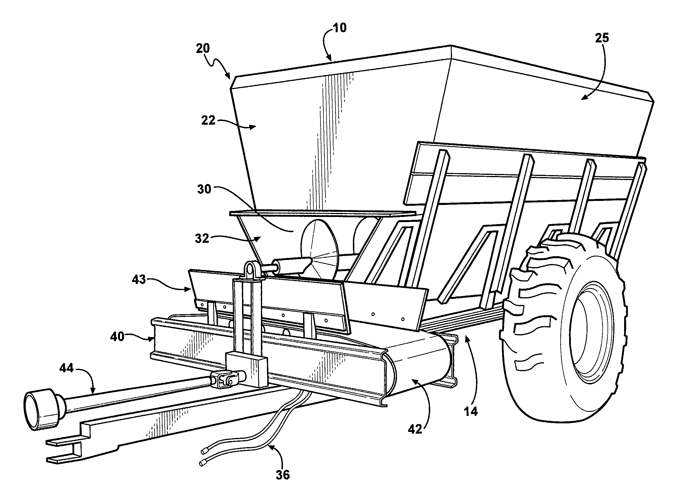
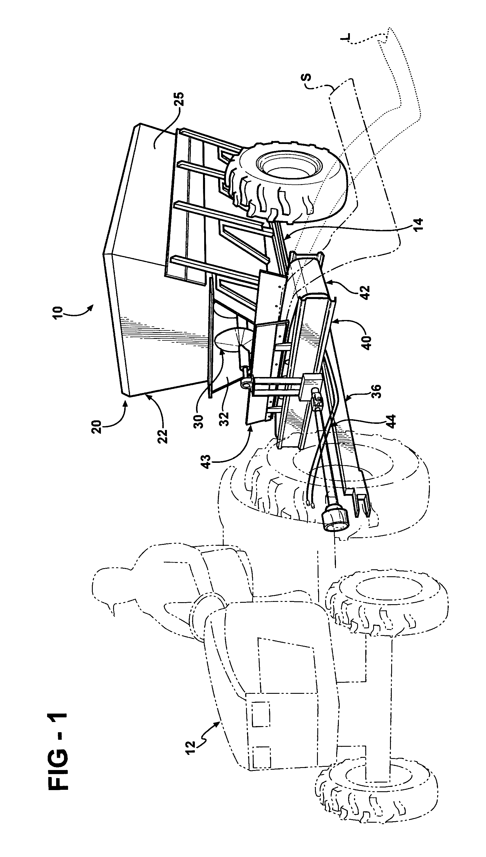
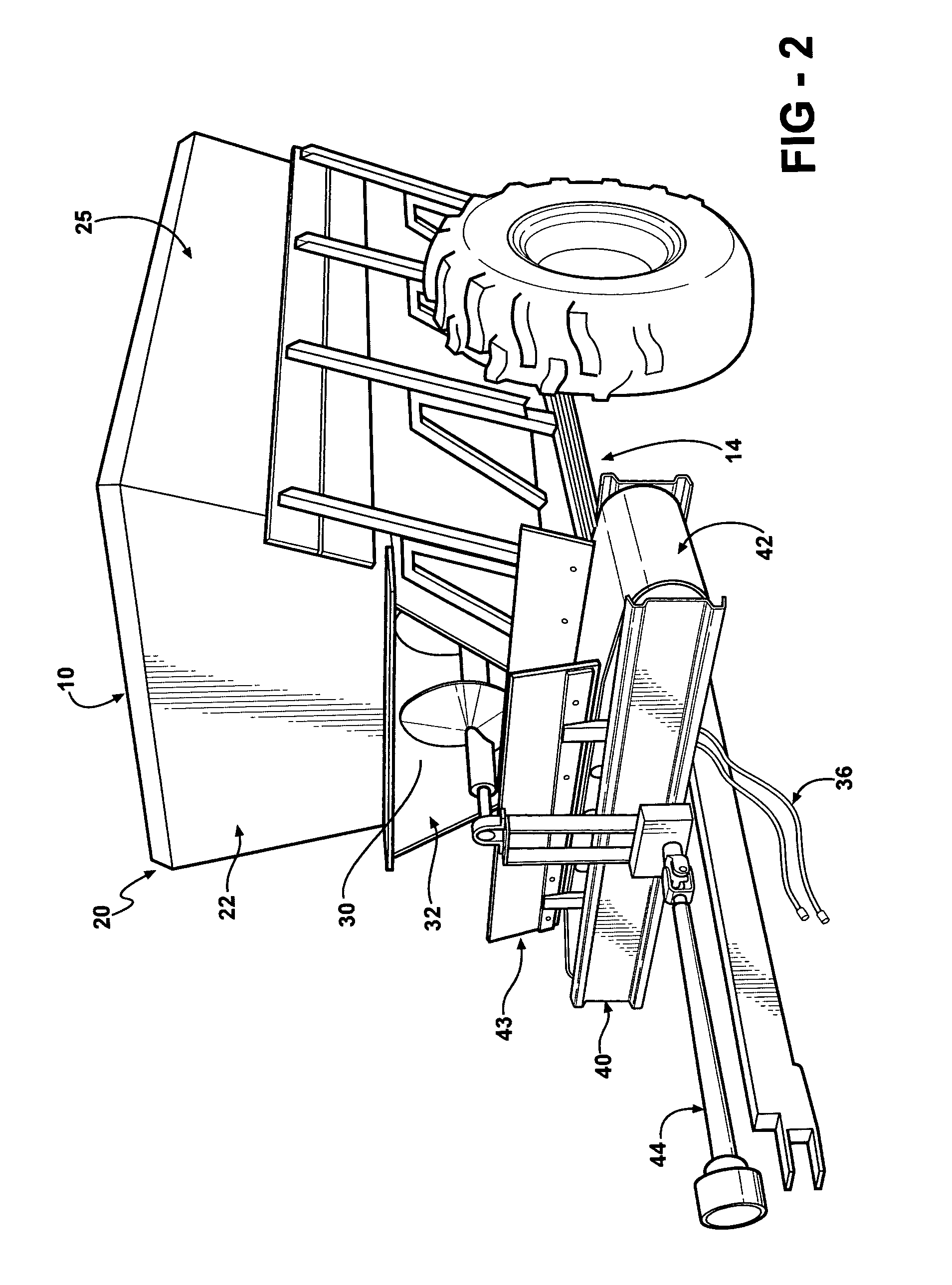
[0008]In yet another feature of the illustrative embodiment of the present invention the improved self-unloading spreader has a front end, a back end, and sides defining walls of a container for holding material. The container is smaller at an enclosed bottom than it is at an open top area. The container has at least one opening in one of the walls through which material can move. Inside of the container, longitudinally disposed between the front end and the rear end, is an auger that can move material in the container to and through the opening. Also inside of the container, adjustably positioned above the auger, is an adjustable height baffle to control the amount of material the auger has available to move. Outside of the container, adjacent to the opening, is a transversely mounted conveyer belt for spreading material that flows through the opening. An hydraulic system powers the auger and allows the hydraulically powered auger to either move material towards the opening or away from the opening. The auger, in combination with the adjustable height baffle, controls the rate at which material is provided to the conveyer system. A power-take-off system transfers power to a gear box system that allows bi-directional movement of the transversely mounted conveyer belt so the conveyer system can spread material to either side of the spreader. The speed of the power-take-off system controls the distance to which the conveyer system throws the material to be spread.

Problems solved by technology

This limits the options an operator of any of these systems has to vary the material spread rate and the throw distance; i.e. the operator can increase these together or decrease these together but not increase / decrease them separately.
Another problem conventional spreaders have is they either spread material to both sides of the spreader at once, as does the rotational spreader in U.S. Pat. No. 3,235,107 (Tift), or they are uni-directional and spread material to only one side, as in U.S. Pat. Nos. 3,520,434 (Destefan, et al), 3,037,780 (Skromme et al) and 3,159,296 (Schuitemaker) and 2,786,655 (Cowsert).

Method used


Image

  • Self unloading pull-type trailer
  • Self unloading pull-type trailer
  • Self unloading pull-type trailer

Examples


Embodiment Construction

[0018]The following descriptions are of an exemplary embodiment only, and are not intended to limit the scope, application of configuration of the invention in any way. Rather, the following descriptions provide a convenient illustration for implementing exemplary embodiments of the invention. Various changes to the described embodiment may be made in the function and arrangement of the elements described without departing from the scope of the invention as set forth in the claims.

[0019]Referring to FIGS. 1 and 2, there is shown an improved self-unloading spreader 10 of the type usually pulled by a tractor 12 (though the spreader could be self-powered as well). The self-unloading spreader 10 has a frame 14 upon which is mounted a container 20 that can contain material that needs to be spread such as dry sand, small stone, topsoil, mulch and many other types of material. The container 20 has a front end wall 22, a read end wall 23, two side walls 24 and 25 and a bottom 26. Together t...


PUM


Abstract

An improved self-unloading spreader has a front end, a back end, and sides defining walls of a container for holding material. The container has at least one opening in one of the walls through which material can move. Inside of the container, longitudinally disposed between the front end and the rear end, is an auger that can move material in the container to and through the opening. Also inside of the container, adjustably positioned above the auger, is an adjustable height baffle to control the amount of material the auger has available to move. Outside of the container, adjacent to the opening, is a transversely mounted conveyer belt for spreading material that flows through the opening. An hydraulic system powers the auger and allows the hydraulically powered auger to either move material towards the opening or away from the opening. The auger, in combination with the adjustable height baffle, controls the rate at which material is provided to the conveyer system. A power-take-off system transfers power to a gear box system that allows bi-directional movement of the transversely mounted conveyer belt so the conveyer system can spread material to either side of the spreader. The speed of the power-take-off system controls the distance to which the conveyer system throws the material to be spread.

Description

FIELD OF THE INVENTION[0001]The present invention relates to self-unloading spreaders and more particularly to a self-unloading spreader in which the rate at which material is spread and the distance material is thrown are independently controllable. In addition the direction in which material is thrown can be easily changed.BACKGROUND OF THE INVENTION[0002]Self-unloading spreaders for materials such as rocks, sand, salt, soil, mulch, and the like are well known. Some are self-powered, such as the spreader disclosed in U.S. Pat. No. 3,235,107 (Tift). Others are meant to be towed and / or powered by another vehicle such as the spreaders disclosed in U.S. Pat. Nos. 3,520,434 (Destefan, et al), 3,037,780 (Skromme et al) and 3,159,296 (Schuitemaker). These spreaders have material moving systems with single power systems such as hydraulics or by the power-take-off of a towing vehicle but not a combination of both. This limits the options an operator of any of these systems has to vary the ...

Claims


Application Information

Patent Timeline
Patent Type & Authority Patents(United States)
IPC IPC(8): A01C3/06A01C15/00A01C7/00E01C19/20A01C19/00F04B17/06
CPCE01C19/201E01C19/2045E01C2019/2075
Inventor ELLING, BRAD
Owner ELLING BRAD
Learn More