
Dual cell rear corner pillar for automobiles

a rear corner pillar and dual cell technology, applied in the field of rear pillar configuration, can solve the problems of increasing the longitudinal length of the roof, increasing the unsupported span over which load must be transferred, and reinforcing the rear pillar, so as to achieve the effect of reducing the number of structural pieces, and being durable in construction

Inactive Publication Date: 2009-06-09
FORD MOTOR CO
View PDF10 Cites 23 Cited by
  • Summary
  • Abstract
  • Description
  • Claims
  • Application Information

AI Technical Summary

Benefits of technology

This patent describes a new design for the rear corner pillar of a pick-up truck that provides better strength and efficiency. The design uses a two-cell design, which allows for a stronger pillar while maintaining a compact size. The front and rear tubular members are nested, providing support for each other, and can be easily attached to other parts of the truck. The design also allows for easy attachment of trim parts and is simple and effective in use. Overall, this design provides greater strength, cost savings, and improved performance for pick-up trucks.

Problems solved by technology

This open span increases the longitudinal length of the roof and, as a result, increases the unsupported span over which load must be transferred to meet roof strength requirements and consequentially increases the moment applied to the base of the rear pillar of the operator's cab in a pick-up truck.
Reinforcing the rear pillar in a pick-up truck is a design problem because the rear pillar conventionally has a large cross-sectional configuration and the packaging restraints include the rear door hinges, the rear door window, the back window and the seat belt restraints.
Adding a large flat reinforcement to the rear pillar section is not likely to provide adequate benefits, as the reinforcement will tend to buckle under the imposed load instead of efficiently transferring the load.

Method used


Image

  • Dual cell rear corner pillar for automobiles
  • Dual cell rear corner pillar for automobiles
  • Dual cell rear corner pillar for automobiles

Examples


Embodiment Construction

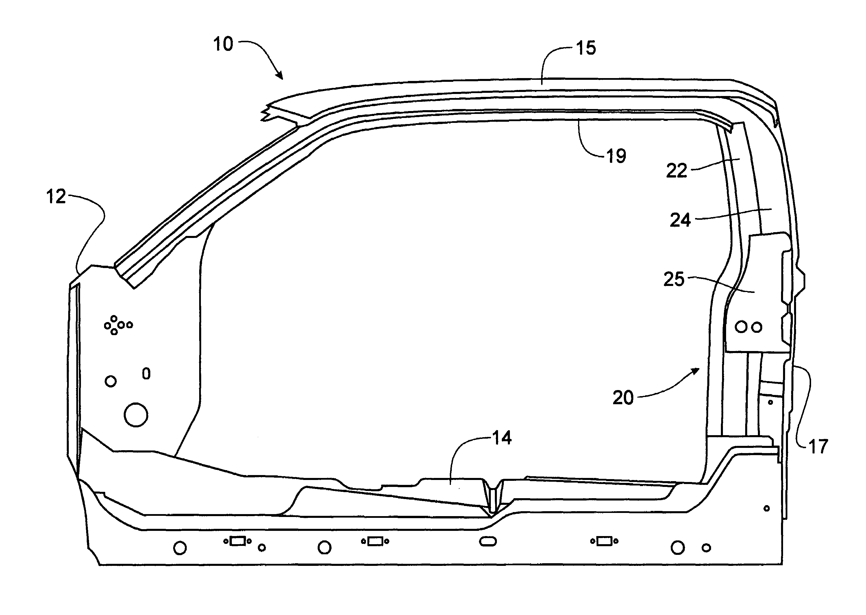
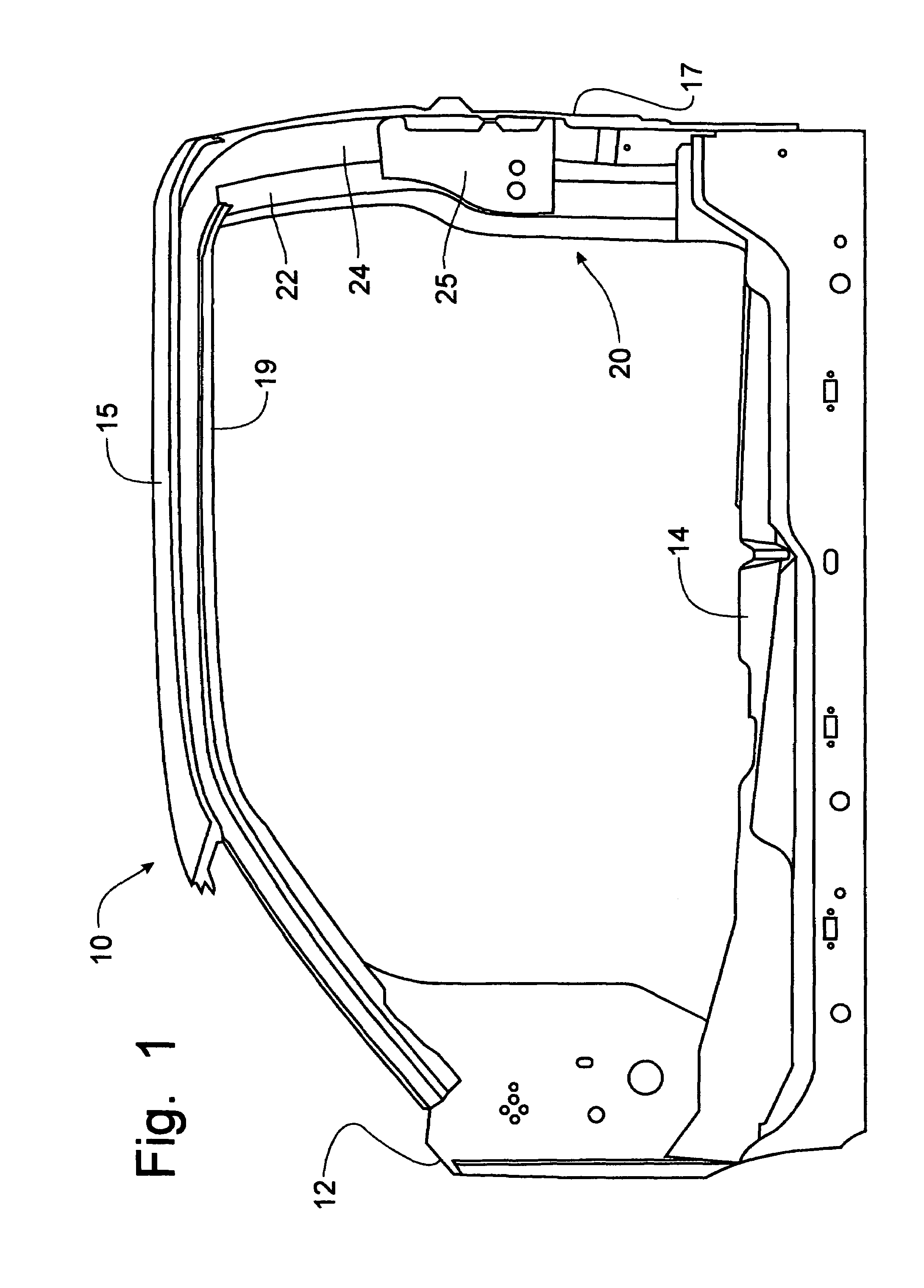
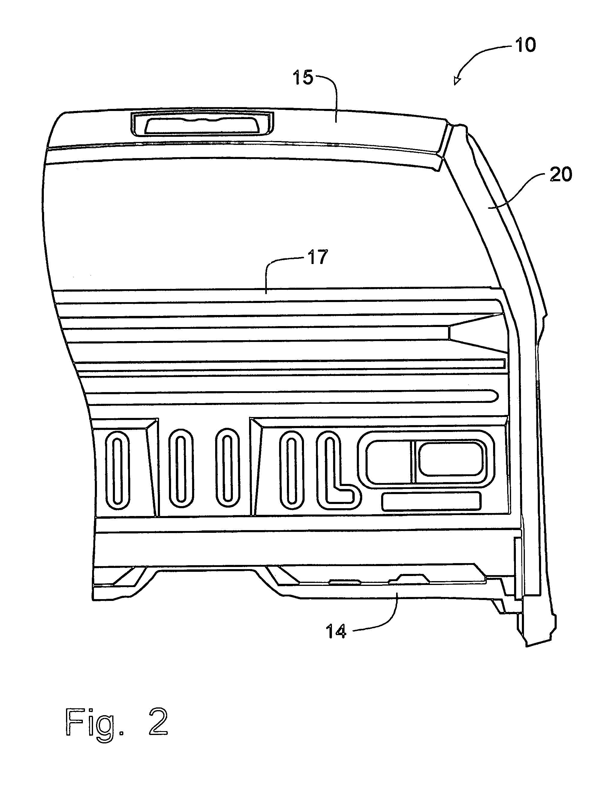
[0029]Referring to FIGS. 15, a frame for the operator's cab of a pick-up truck can be seen. The frame 10 of the operator's cab includes a rear corner pillar structure that incorporates the principles of the instant invention. Any left and right references are used as a matter of convenience and are determined by standing at the rear of the operator's cab and facing the normal direction of travel of the pick-up truck. The frame 10 of the operator's cab is formed with a generally vertical front (or “A”) pillar 12 extending between the floor member 14 and the roof 15. A rear pillar 20 completes the generally rectangular configuration of the frame 10 and is intended to encompass both front and rear doors (not shown). The front door will hinge on the front “A”pillar 12, while the rear “B”pillar will support the hinges for the rear door. A back panel 17, as well as the roof member 15, extends from one side of the vehicle frame 10 to the other, spanning between the transversely spaced rear...


PUM


Abstract

A dual cell rear corner pillar for the operator's compartment of a pick-up truck is formed with longitudinally oriented front and rear tubular members. The dual cell tubular construction increases section strength for the rear corner pillar while maintaining packaging constraints for the rear pillar design. The front tubular member is nested against the rear tubular member to provide support therefor longitudinally and vertically. The forward tubular member is welded to the door opening panel seal flange, while the rearward tubular member is welded to the window flange and the back panel flange. The forward and rearward tubular members are also welded to one another to form a strong pillar structure. The dual cell configuration resists buckling and shares loading. The rear tubular member wraps around the front tubular member and transitions into the roof rail area, shortening the unsupported moment arm of the rear tubular member.

Description

FIELD OF THE INVENTION[0001]This invention relates to the frame of an automotive vehicle and, more particularly, to a rear pillar configuration particularly adapted for use in pick-up trucks.BACKGROUND OF THE INVENTION[0002]The frame of an automotive vehicle supports an operator's compartment and includes a roof supported by generally vertical members commonly referred to as pillars. For vehicles referred to as pick-up trucks, the roof is normally supported by front and rear pillars, also known as the “A” and “B” pillars. The frame of the vehicle is required to withstand certain forces relating to crashes of the vehicle. Those crash standards help determine the configuration of the vehicle frame. Pick-up trucks are often designed with an enlarged operator's compartment that includes a rear passenger seat and a set of rear doors that can be hinged on the rear pillars to provide an open span between the front and rear pillars when the front and rear doors are opened.[0003]This open sp...

Claims


Application Information

Patent Timeline
Patent Type & Authority Patents(United States)
IPC IPC(8): B62D25/04
CPCB62D21/15B62D25/04
Inventor DAY, FRANKLOWE, JAMESREED, JOHN
Owner FORD MOTOR CO
Learn More