Pin milling cutter

a technology of milling cutter and pin, which is applied in the direction of shaping cutter, attachable milling device, manufacturing tools, etc., can solve the problems of increasing the number of types of engagement sections, inconvenient installation of cutters on adapters, and defective cutting parts, so as to prevent mounting errors, reduce labor intensity, and prevent the effect of machining and installation of the mechanism

Active Publication Date: 2009-06-09
SUMITOMO ELECTRIC HARDMETAL CORP
View PDF14 Cites 8 Cited by
  • Summary
  • Abstract
  • Description
  • Claims
  • Application Information

AI Technical Summary

Benefits of technology

[0010]In order to overcome these problems, the present invention provides an improvement for a pin milling cutter for cutting crankshafts wherein a cutter has a cutting section on an inner perimeter or an outer perimeter of a ring-shaped main cutter body. Further, an adapter supporting the cutter, along with the cutting section, are formed with engagement projections and cavities aligned to each other and positioned at mutually fitting sections at a fixed pitch along a circumference, the engagement projections and cavities provide a tapered fitting so that the cutter and the adapter can be concentrically removably combined. In the present invention, the pin milling cutter is formed so that a mounting error preventing mechanism is provided on the main cutter body and the adapter to prevent the cutter and the adapter from being fitted to each other incorrectly, e.g., at a mistaken position.
[0016]With the pin milling cutter of the present invention, the mounting error preventing mechanism prevents the cutter and the adapter from being fitted if a bad combination of cutter and adapter is used. Thus, even if the engagement sections of the cutter and adapter are standardized, mounting errors are prevented, eliminating the need to use a method that is disadvantageous in terms of effort, costs, maintenance, and the like.
[0017]The mounting error preventing mechanism is formed as a corresponding projection and groove to keep the structure simple and to allow the machining and installation of the mechanism to be performed easily.
[0018]The use of removable cap screw or pin for the projection makes it possible for the projection attached to the adapter to be replaced with one for grooves having a fitting section with a different size. Also, by changing the attachment position of the projection, the same adapter can be combined with cutters having different specifications. As a result, when the cutter is replaced with one of a different type, the adapter does not need to be replaced, making it possible to standardize the adapter.
[0019]In addition, the groove into which the projection is inserted is formed as a groove extending all the way from one surface to the other so that the groove can be easily machined. Also, the use of a single projection and a plurality of grooves formed at a pitch at which the engagement section described above are formed or a pitch that is an integer multiple thereof allows the projection and the grooves forming the mounting error preventing mechanism to fit together even when the engagement positions of the engagement sections of the cutter and the adapter are changed. Thus, the attachment orientation of the cutter to the adapter is not restricted.

Problems solved by technology

However, when inserts with similar shapes are present in a cutter which has had its cutting edge replaced, an inappropriate cutter may be installed on an adapter by mistake.
This will result in all the cut parts being defective.
While cutters with high-precision engagement sections can prevent inappropriate combinations of cutters and adapters by using different widths, outer diameters, and shapes for the tapered splines and spline grooves, using this method will increase the number of types of engagement sections and will lead to issues such as the inconvenience of gauge inspections, production costs, and administration.

Method used


Image

  • Pin milling cutter
  • Pin milling cutter
  • Pin milling cutter

Examples


Embodiment Construction

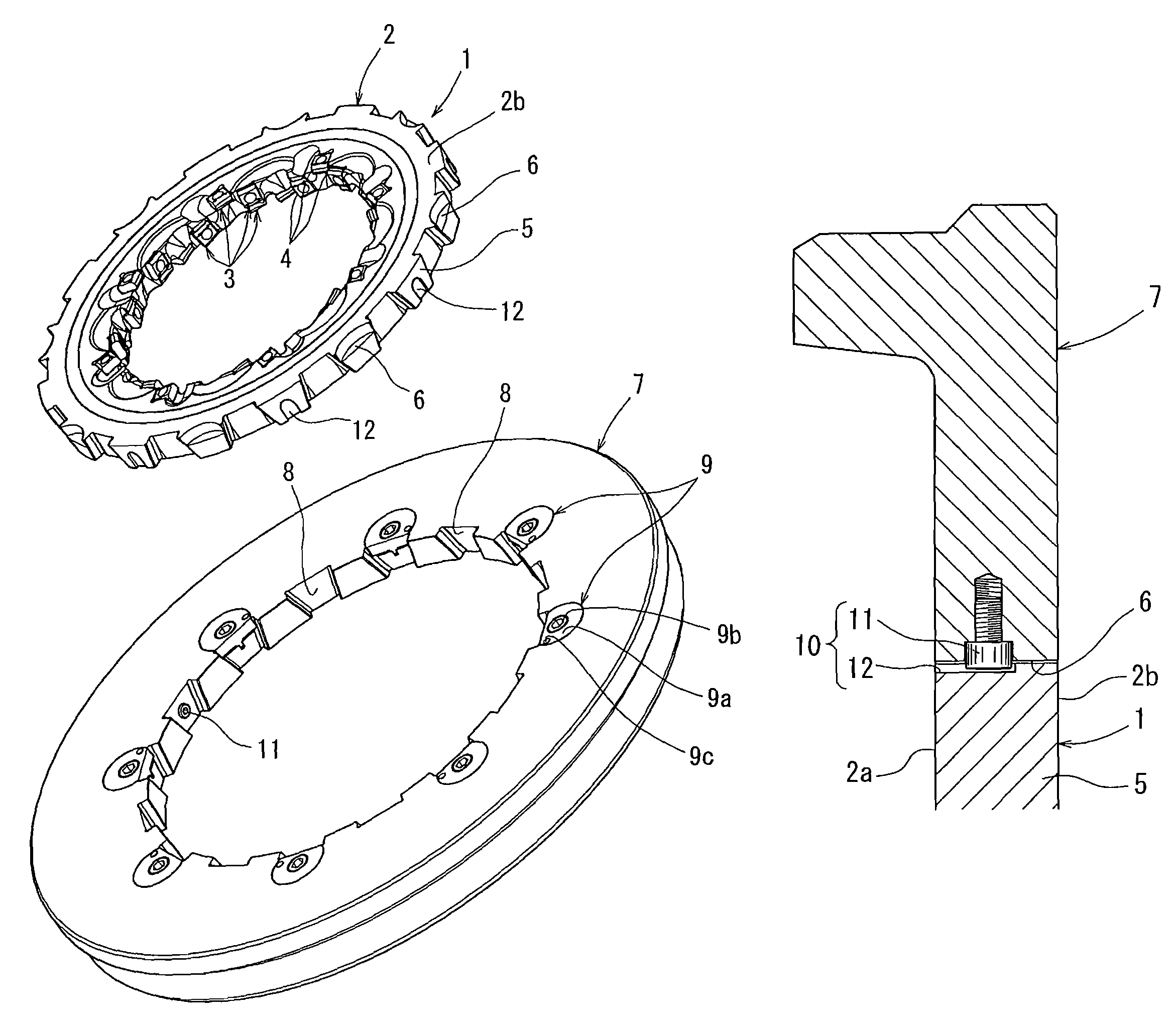
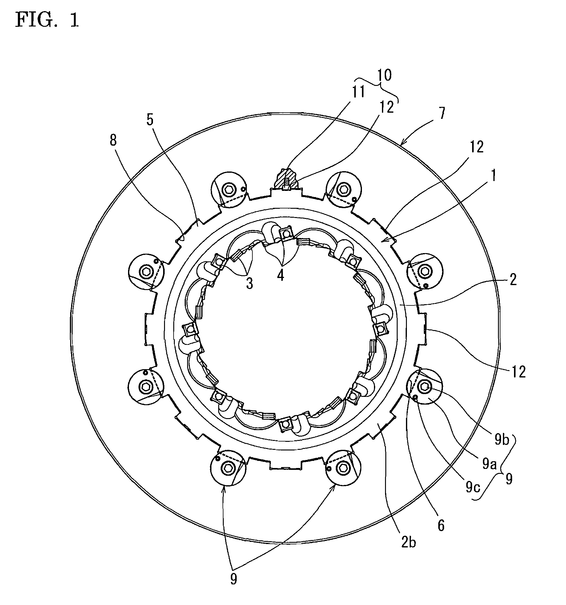
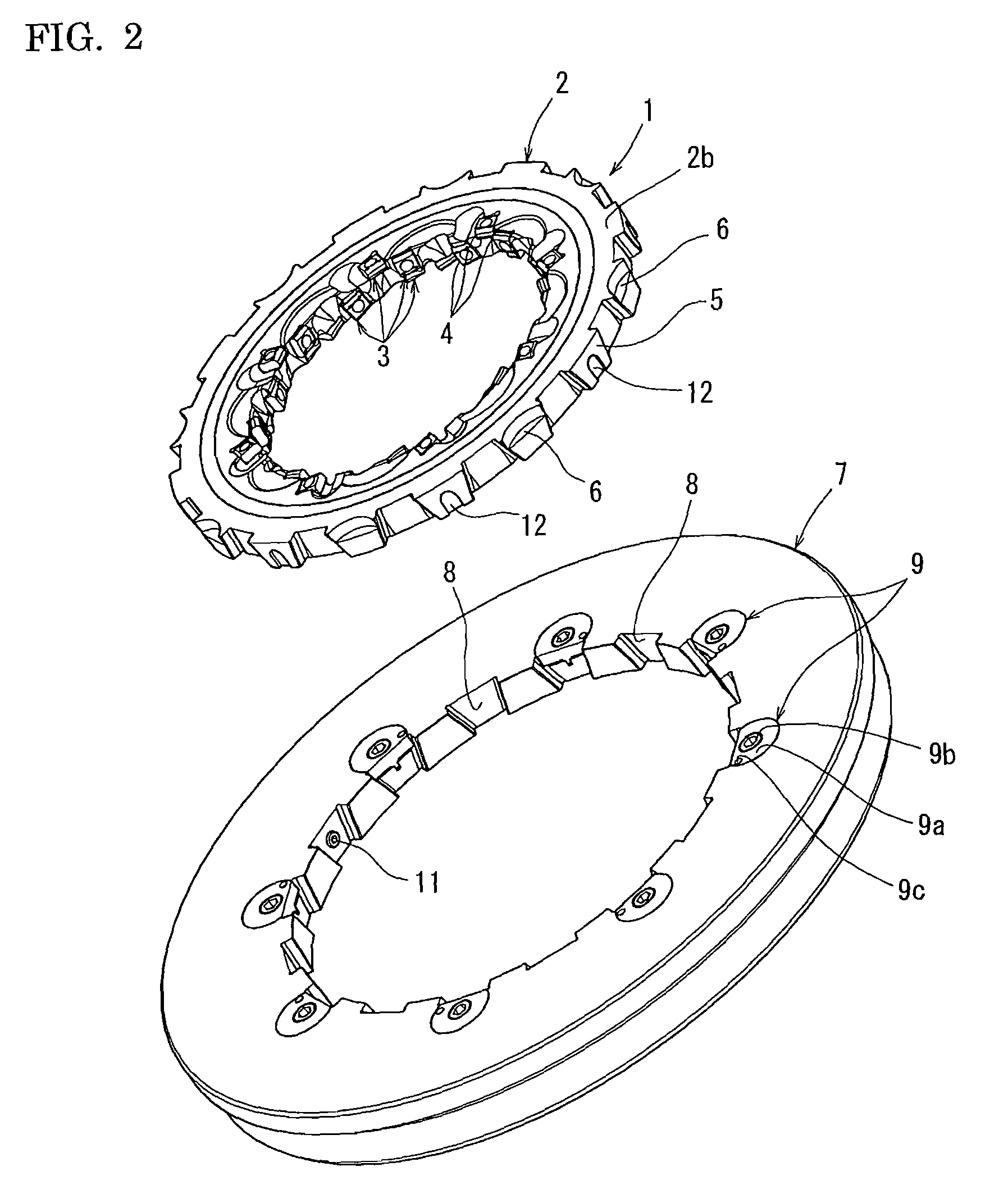
[0030]Referring to FIG. 1 through FIG. 10, the embodiments of the pin milling cutter of the present invention will be described. The cutter of this example in an internal pin milling cutter and includes a cutter 1 and an adapter 7. The inner diameter of the cutter 1 is fitted and supported by the adapter 7. The cutter 1 is formed with a ring-shaped main cutter body 2, and replaceable cutting edge inserts 3 are mounted on the inner perimeter side thereof. The edges of the inserts 3 form cutting sections 4. The replaceable cutting edge inserts 3 are used in combination so that multiple inserts work together on the region of the crank shaft to be cut. Edges damaged from cutting are switched, and when all edges that can serve as cutting sections 4 have been used, replacement is performed.

[0031]Projections 5 are formed at a fixed pitch along the outer perimeter of the main cutter body 2 and are projected outward to engage with the adapter 7. In one embodiment, the projections 5 can be ta...


PUM

PropertyMeasurementUnit
circumferenceaaaaaaaaaa
perimeteraaaaaaaaaa
widthaaaaaaaaaa

Abstract

The present invention provides a pin milling cutter formed by combining a cutter and an adapter to prevent errors in attaching a cutter to the adapter even when the cutter is similar but of a different type and even if the engagement section between the cutter and the adapter are the same. A mounting error prevention mechanism is provided on a main cutter unit and an adapter to prevent an erroneous combination of a cutter and adapter from fitting together normally. The mounting error prevention mechanism includes: a projection and a cavity corresponding to the main cutter unit and the adapter and providing a tapered fit; and a projection and a corresponding groove. The projection can be inserted into the groove only when the cutter and the adapter are combined correctly.

Description

INCORPORATION BY REFERENCE[0001]The present application claims priority under 35 U.S.C. §119 to Japanese Patent Application No. 2005-354966 filed on Dec. 8, 2005. The content of the application is incorporated herein by reference in its entirety.BACKGROUND OF THE INVENTION[0002]1. Field of the Invention[0003]The present invention relates to a pin milling cutter for crank shafts in which a cutter and adapter are combined.[0004]2. Description of the Background Art[0005]Examples of pin milling cutters include the ones disclosed in Japanese Patent Publication Number 2861828, Japanese Laid-Open Patent Publication Number 2004-283934, Japanese Laid-Open Patent Publication Number 2004-283935, and Japanese Laid-Open Patent Publication Number 2004-314194.[0006]The pin milling cutters disclosed in Japanese Patent Publication Number 2861828, Japanese Laid-Open Patent Publication Number 2004-283934, Japanese Laid-Open Patent Publication Number 2004-283935, and Japanese Laid-Open Patent Publicati...

Claims


Application Information

Patent Timeline
Patent Type & Authority Patents(United States)
IPC IPC(8): B23C3/06
CPCB23C3/06B23C5/12B23C5/2234B23C2200/367B23C2210/16B23C2210/503Y10T82/19B23C2260/68Y10T407/22Y10T407/1908Y10T409/30952Y10T407/1952B23C2220/68B23C5/2309
Inventor EMOTO, SHIGENORINAKAMURA, AKIO
Owner SUMITOMO ELECTRIC HARDMETAL CORP
Why Eureka
Try Eureka