Flexible shaft coupling system with antirotational features

a flexible shaft and coupling technology, applied in the field of mechanical couplings, can solve the problems of affecting the implementation and performance of the coupling, the existing coupling, and the difficulty of installation and implementation, and achieve the effects of reducing the required assembly dead space, facilitating installation, and minimizing the radial profile of the coupling system

Inactive Publication Date: 2009-06-09
BALDOR ELECTRIC COMPANY
View PDF8 Cites 6 Cited by
  • Summary
  • Abstract
  • Description
  • Claims
  • Application Information

AI Technical Summary

Benefits of technology

[0011]The present invention offers a coupling arrangement that addresses some or all of the issues and problems that currently limit other commercially available mechanical couplings. The invention generally consists of three parts, a first hub assembly, a second hub assembly, and a flexible element placed therebetween. Each hub assembly mounts to a shaft or other rotating member, and includes elements that are used to capture a periphery of the flexible element. The complaint nature of the flexible element allows for misalignment between the respective shafts as well as functioning as a dampener for shock and vibration isolation.
[0012]The innovative design of the current invention also eliminates the need to align multiple coupling elements in order to secure the coupling to the rotating members and to one another. This allows for the coupling to be easily installed and implemented into a mechanical system. The current invention also reduces the required assembly dead space, as well as minimizes the radial profile of the coupling system. These benefits were realized by configuring and arranging fasteners to compress the elements together. The resulting configuration minimizes the length of the fastener thereby reducing assembly dead space. The arrangement may also eliminate the need for the fastener to pass through the flexible element thereby reducing the radial profile of the coupling. Furthermore, this configuration may allow for the clamping force to be directly applied and evenly distributed to the outer periphery of the flexible element.
[0013]Finally, the current invention incorporates a positive locking feature to avoid the self-loosening that could result from shock and vibration. The fasteners used to clamp the flexible element can be configured to engage a recess in the rotatably fixed clamping element to prevent the adjusting nut from rotating or self-loosening.

Problems solved by technology

All of these have limitations that impact the implementation and performance of the coupling when used in a mechanical system.
One limitation is that existing couplings have a number of parts that have to be aligned in order to engage the coupling.
The interaction and physical configuration of these parts often make them difficult to install and implement, as well as to service.
Such difficulties lead to increased installation time and system downtime when servicing is required, particularly when the coupling is used in an application where direct access is limited.
In this situation, the user has the difficult task of blindly aligning and engaging these coupling elements.
The process of visually aligning these elements becomes tedious and time consuming when visual access to the coupling is limited.
Furthermore, the installation task becomes even more difficult when alignment or interaction between more than two coupling elements is required.
Another limitation is that the couplings can be bulky and require more installation space than is available.
In particular, the coupling might require excess installation room for engaging items such as the fasteners discussed above.
Furthermore, the radial profile of mechanical couplings can also make installation and servicing difficult.
A further limitation results from the misalignment of the coupled shafts.
Practically speaking, this misalignment can never be completely eliminated.
Some commercially available couplings address the misalignment issue by implementing a flexible element into the coupling, but often do so at the cost of reduced torque carrying capacity.
This limitation may result from not applying the clamping force directly to the outer periphery of the element being captured, or from the forces being unevenly distributed across this periphery.
The end result is that the torque carrying capacity of the coupling is reduced because the captured element may tend to peel out of the clamping mechanism.
Another issue arises as a result of dynamic imbalances inherent in any rotating device.
At high rotational velocities these imbalances can result in severe lateral, torsional, and axial vibrations that are then transmitted through the system via the coupling.
These vibrations cause the system to run less efficiently and can also damage vibration sensitive devices, such as bearings.
The vibrations discussed above can cause these threaded members to be unthreaded.
When this self-loosening occurs, the forces holding the coupling together are no longer present, potentially permitting the coupling to disengage.

Method used


Image

  • Flexible shaft coupling system with antirotational features
  • Flexible shaft coupling system with antirotational features
  • Flexible shaft coupling system with antirotational features

Examples


Embodiment Construction

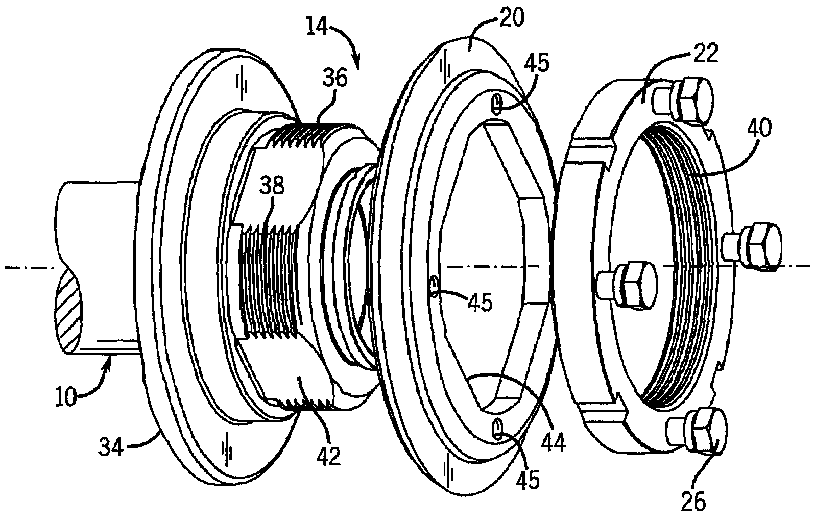
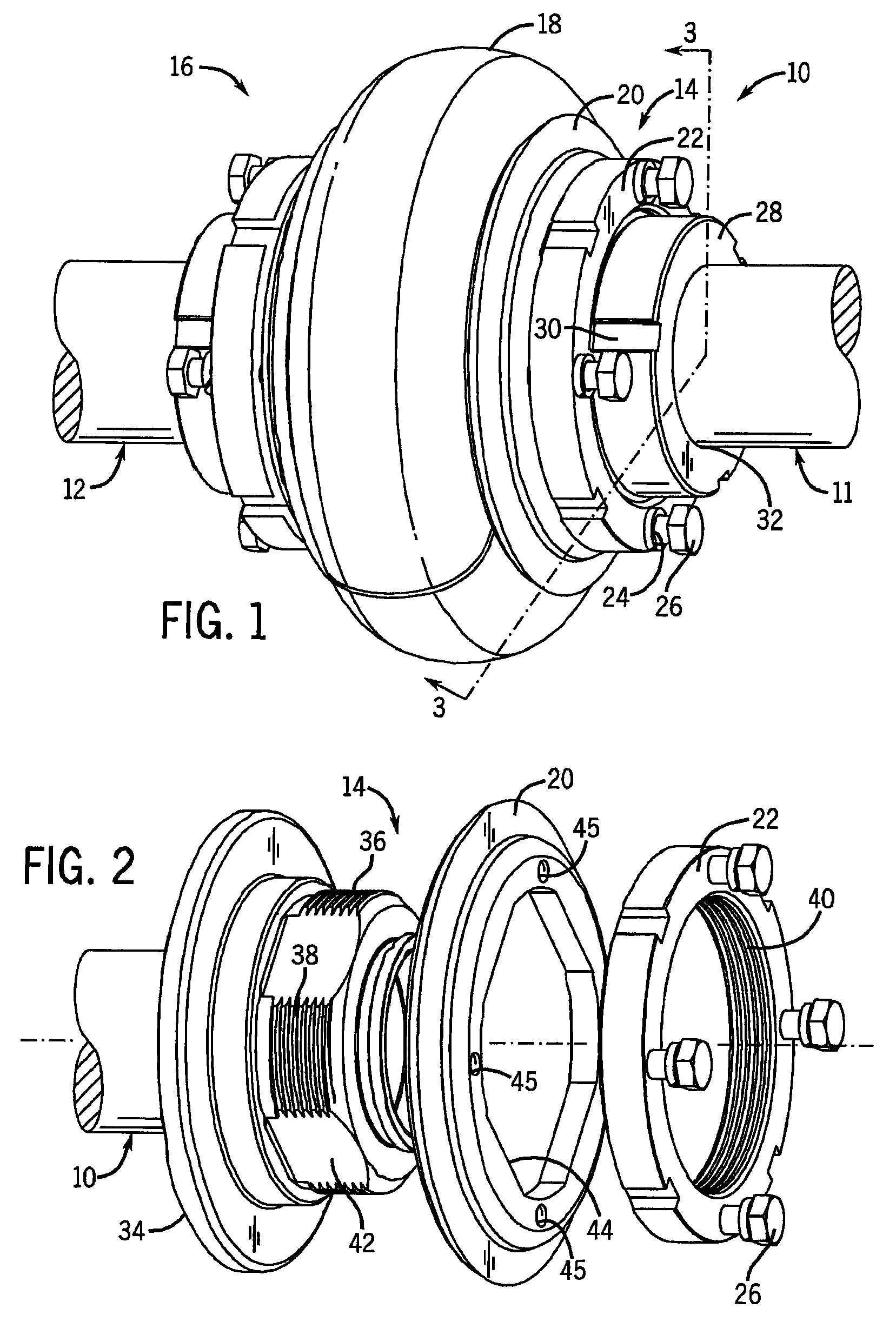
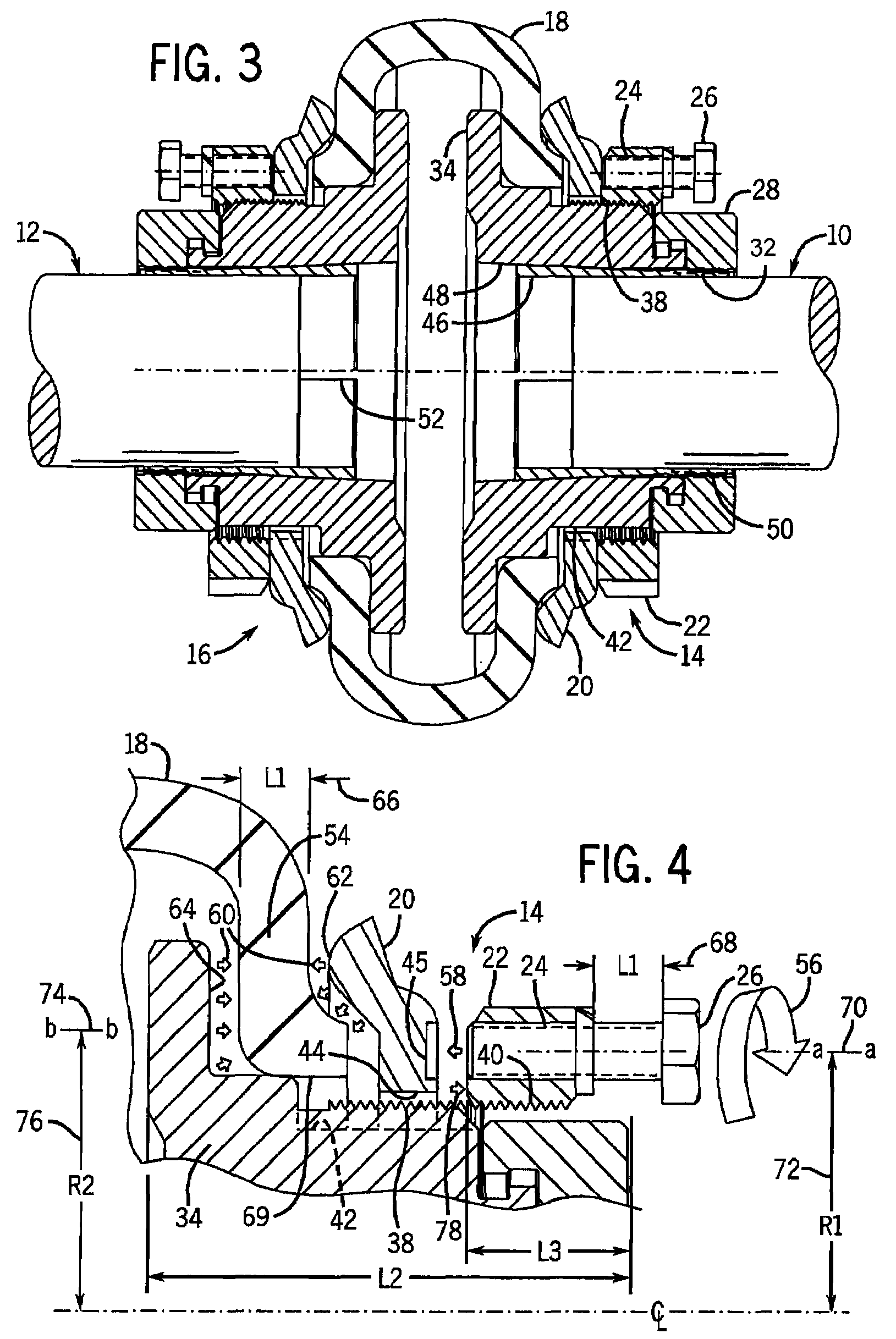
[0020]Turning now to the drawings, FIG. 1 illustrates a first rotating shaft 10 coupled to a second rotating shaft 12 via a flexible shaft coupling system. The system comprises a first hub assembly 14 coupled to a second hub assembly 16 via a flexible element 18. The hub assemblies may be mirror images of one another, as in the illustrated embodiment, although this need not be the case, and different hubs may be used to accommodate differently sized shafts.

[0021]As shown for the hub on the right side of the system illustrated in FIG. 1, the flexible element 18 is coupled to the hub assembly via a flange 20 and adjusting nut 22. The flexible element is made from a compliant elastomeric material such as a reinforced natural rubber or neoprene. Those skilled in the art will readily appreciate that the invention is not functionally limited to these specific material choices and any suitable compliant material could be used for the flexible element. The compliant nature of the flexible e...


PUM


Abstract

A coupling system is disclosed for coupling rotating elements such as a pairs of shafts, flywheel and a shaft, and so forth. A first hub assembly is attached to a shaft via a tapered sleeve mechanism. A flexible element is captured by the hub assembly and is used to couple one rotating member to another. The hub assembly includes a hub, a flange, and an adjusting nut that are used in conjunction with fasteners to compress the flexible element. The flange has anti-rotation features that engage similar features on the outside diameter of the hub. The adjusting nut has internal threads that engage external threads on the hub outside diameter. The flexible element either mounts directly to the second rotating element or is captured by a second hub assembly. The second hub assembly is attached to the second shaft via a tapered sleeve mechanism.

Description

BACKGROUND[0001]The current invention relates to the field of mechanical couplings. More specifically, the invention relates to an improved flexible coupling system for coupling a shaft of one rotating member to a shaft or flywheel of another rotating member.[0002]Mechanical systems often consist of a number of energy converting devices. A few examples of such devices include engines, motors, pumps, alternators, generators, and turbines. These devices are often physically connected to one another via a mechanical coupling to realize the potential of one energy source by converting it into a more useful form. For example, the rotating shaft of an internal combustion engine may drive a flywheel that is, in turn, coupled to the shaft of a pump or other driven device. The mechanical coupling serves to transfer the kinetic energy generated by the engine to drive the load, particularly by transmitting torque to the load during operation.[0003]A variety of mechanical couplings are known an...

Claims


Application Information

Patent Timeline
Patent Type & Authority Patents(United States)
IPC IPC(8): F16D3/58
CPCF16D3/74F16D2003/745
Inventor NISLEY, DONALD L.
Owner BALDOR ELECTRIC COMPANY
Why Eureka
Try Eureka