Sighting device and additional device for measuring, working, and/or operating with or without contact

a technology of a sighting device and an additional device, which is applied in the direction of surveying, navigation, weapons, etc., can solve the problems of difficult compensation, reducing the effective aperture of the infrared measurement channel, and introducing central holes in the objective is relatively expensive, so as to achieve the effect of avoiding unnecessary losses, simple adjustment, and high economic production of optical components

Inactive Publication Date: 2009-06-09
OPTRIS
View PDF19 Cites 7 Cited by
  • Summary
  • Abstract
  • Description
  • Claims
  • Application Information

AI Technical Summary

Benefits of technology

[0009]In a manner according to the invention it has first been recognized that components of a sighting device which are located on the axis of the measuring, working, and / or operating device have an interfering effect on the measurement process and even make a work process impossible under certain circumstances. Moreover, it has been recognized that through the splitting, according to the invention, of two sighting rays by means of optical components into two intersecting illumination planes a visible target marking in the form a of crosshairs can be generated. In so doing, the target marking, independently of the distance of the measured objects, is always located exactly on the axis of the measuring or operating device without any interfering components being disposed on the axis. Consequently, a parallax-free, distance-independent sighting is possible as a result.
[0011]The two sighting devices thus produced are each directed onto one optical component, where each of the two optical components splits one of the two sighting rays into an illumination plane, that is, into a fan ray. To avoid unnecessary losses, i.e. for the generation of as bright as possible visible crosshairs, the optical components could be produced of a material with good transmission properties. In an advantageous manner materials such as glass, plexiglass, or transparent plastic could thus be used, which in addition has the advantage that the optical components can be produced extremely economically.
[0012]To split the sighting ray during its passage through the optical component it could comprise at least one, concave or convex, curved surface. In regard to easy handling and simple adjustment circular or semi-circular surfaces present themselves in particular, where elliptical or even asymmetrically curved surfaces would also be conceivable in principle. It is only important here that the sighting rays strike the optical component at different angles in such a manner that after passing through the optical component a splitting of the sighting ray is achieved.
[0028]Instead of the measuring device a working or operating device could be provided which could, for example, be a drilling machine or a surgical instrument. In the case of drilling machines or similar devices there is in general the problem that the drilling process must be carried out in several individual steps. First, a target marking at the desired target location on the object must usually be generated by hand. Then the drill, in the idle state, is mounted on the target marking, and only thereafter is the drill driven and caused to rotate. When using the rotating drill, slipping of the drill from the target marking occurs frequently, which as a consequence has an imprecise and unclean processing as a result. In the case of a drilling machine with the sighting device according to the invention on the other hand, the drill can already have been set in rotation before the actual mounting of the drill on the object to be processed since the target marking, i.e. the intended point of mounting point of the drill on the object, is already visible. Through the visible target marking a rapid forward movement of the drill head even under conditions of rotation is simplified.

Problems solved by technology

In so doing however, a series of problems arises.
Due to the special processing of the infrared-optical materials the introduction of central holes in the objective is relatively expensive.
The structural elements for measurement center sighting reduce the effective aperture of the infrared measurement channel due to their size.
In addition to this, due to their self-radiation they represent, in particular in the case of changes of temperature in the device or object, an interfering variable which is difficult to compensate in the optical channel.
Furthermore, diffraction phenomena occurring at the edges related to construction cause a reduction of the geometric resolution.

Method used


Image

  • Sighting device and additional device for measuring, working, and/or operating with or without contact
  • Sighting device and additional device for measuring, working, and/or operating with or without contact
  • Sighting device and additional device for measuring, working, and/or operating with or without contact

Examples


Embodiment Construction

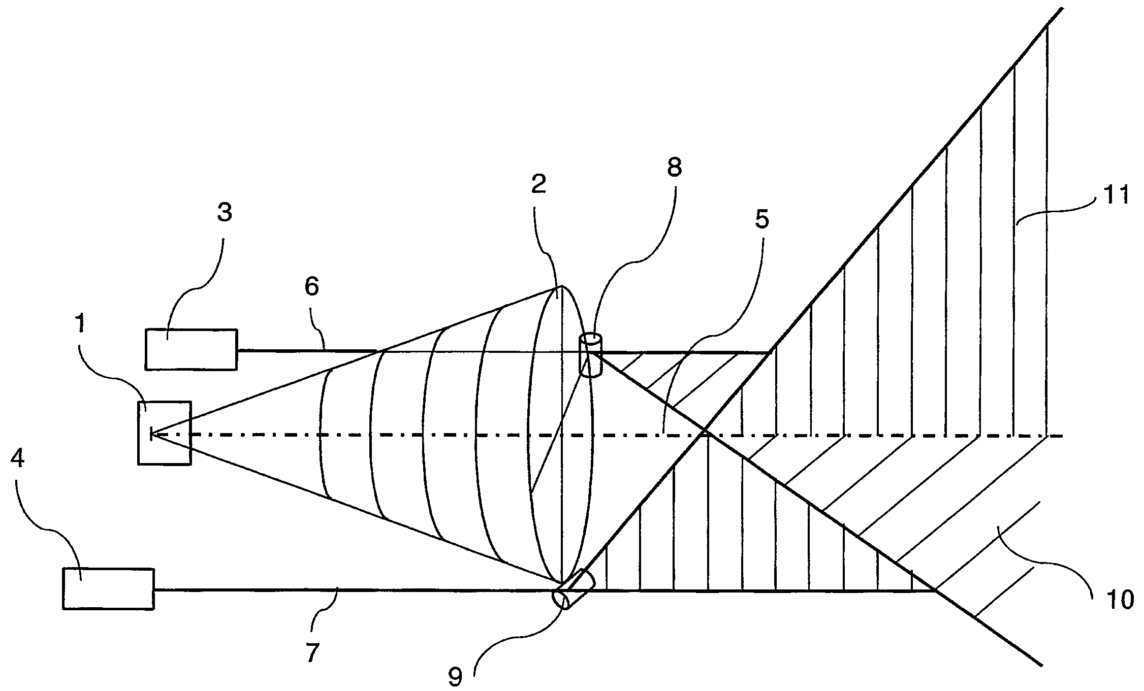
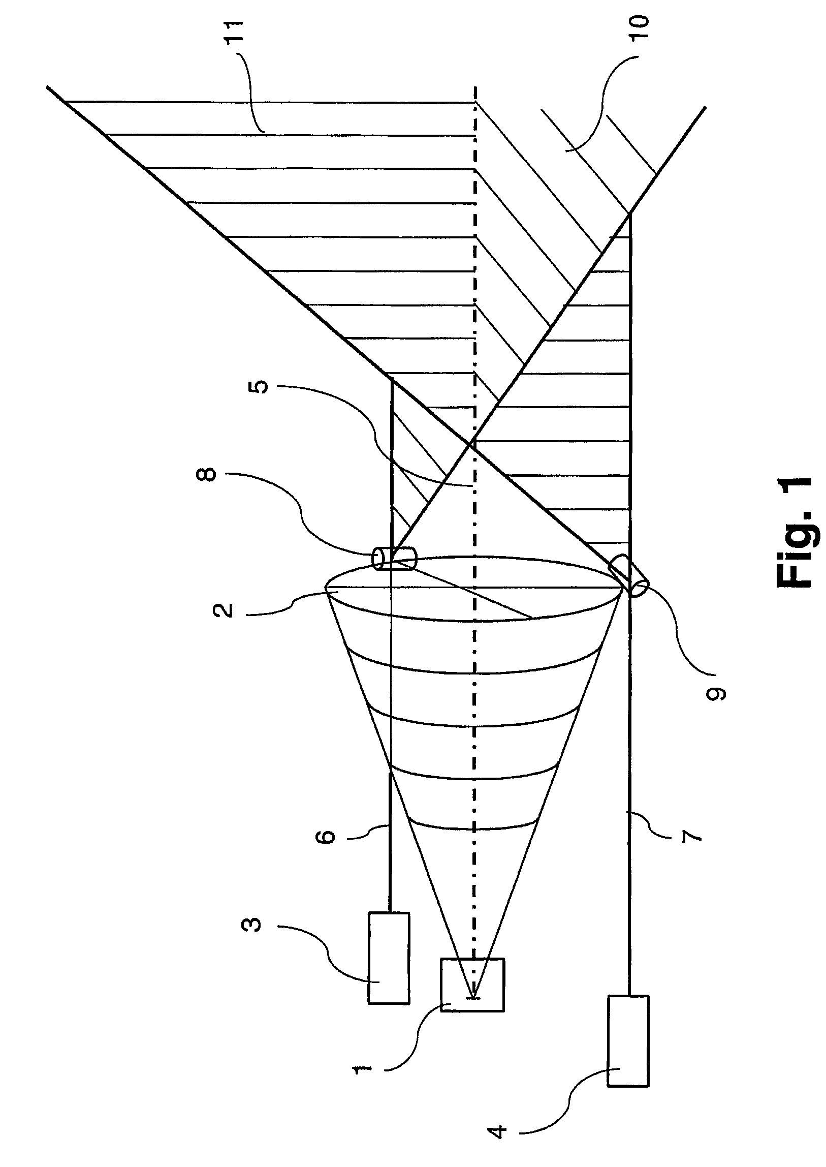
[0040]FIG. 1 shows in a schematic side view a first embodiment example of a device according to the invention with a measuring device which can be used without contact and works interactively with an object of any type at a predetermined target location, where the target location's position can be fixed by means of a sighting device. The device comprises a detector 1 on which the electromagnetic radiation originating from a measured spot on an object not represented can be imaged by means of a lens 2.

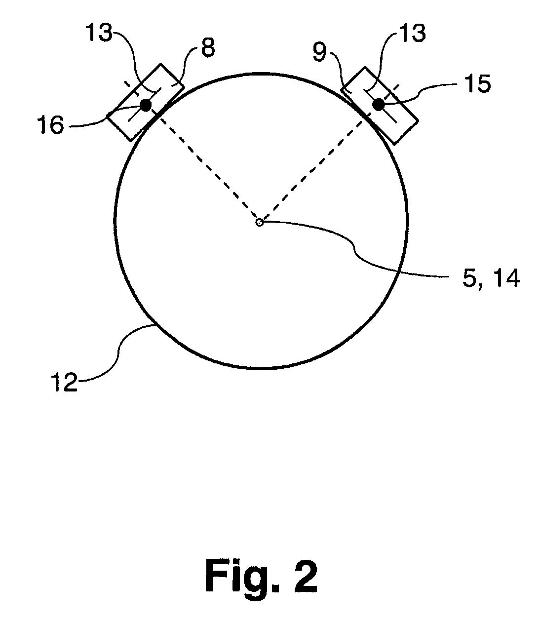
[0041]The sighting device includes two lasers 3, 4 which are disposed to the side of the optical axis 5 of the detector 1. The lasers 3, 4 generate two sighting rays 6, 7 which run parallel to the optical axis 5 of the detector 1 and strike two optical components 8, 9 disposed on the outer circumferential surface of the lens 2. The first laser 3 and the associated optical component 8 are located, according to the perspective representation in FIG. 1, behind the optical axis 5 while the ...


PUM


Abstract

A sighting device is provided which is used to produce an optically perceptible target marking on an object. The sighting device includes one or more light sources for providing at least two sighting rays. A precision target marking is produced in such a manner that each of the sighting rays is directed onto a respective optical component enabling both of the sighting rays to be split on a respective illumination plane in such a manner that at least two illumination planes intersect at an angle. The point of intersection forms the target marking. A measuring, working and / or operating device is optionally provided which can be used with or without contact and which interacts with an object of any type at a predetermined target location. The target location can be detected by means of the inventive sighting device.

Description

CROSS-REFERENCE TO RELATED APPLICATIONS[0001]This application is a continuation of, and claims the benefit of priority to international PCT application number PCT / DE2004 / 001427, which was filed on Jul. 5, 2004, and which designates the United States. The disclosure of the referenced international PCT application is hereby incorporated herein by reference.FIELD OF THE INVENTION[0002]The invention relates to a sighting device for the generation of an optically perceptible target marking on an object with at least one light source to produce two sighting rays. Furthermore, the invention relates to a device with a measuring, working, and / or operating device which can be used with or without contact, where that device interacts with an object of any type at a predefined target location which can be fixed by means of the sighting device.BACKGROUND OF THE INVENTION[0003]Sighting devices and devices of the type coming into consideration here have been known in practice for a long time and f...

Claims


Application Information

Patent Timeline
Patent Type & Authority Patents(United States)
IPC IPC(8): G01C9/00F41G7/26G01J5/08
CPCF41G7/263G01J5/08G01J5/0803G01J5/0831G01J5/0859G01J5/089G01J5/0896G01J5/07
Inventor KIENITZ, ULRICH
Owner OPTRIS
Why Eureka
Try Eureka