Variable geometry inlet guide vane

a technology of inlet guide and variable geometry, which is applied in the direction of machines/engines, stators, liquid fuel engines, etc., can solve the problems of turbulent and even pulsating flow into the engine, increased wear on the components downstream of the inlet guide vane, and the problem of the known inlet guide vanes. to achieve the effect of improving the flow from the flap and avoiding flow separation

Active Publication Date: 2009-06-23
RTX CORP
View PDF10 Cites 40 Cited by
  • Summary
  • Abstract
  • Description
  • Claims
  • Application Information

AI Technical Summary

Benefits of technology

[0006]The present invention provides an inlet guide vane that avoids separation of flow even at high incidence angles. Generally, the strut and the flap are designed together so that low momentum air in the gap between the strut and the flap will be energized and entrained in the boundary layer of the flap. The airflow from the gap will remain attached to the flap to improve the flow from the flap.
[0007]In one embodiment, the strut has opposite side surfaces that are continuously curved to provide a controlled velocity distribution at the trailing edge of the strut. The flap has a leading edge aligned behind the trailing edge of the strut. The flap includes a pressure side surface having a peak spaced away from the leading edge. A suction side surface of the flap has a peak spaced further away from the leading edge than the peak on the pressure side surface, to provide a more gradual acceleration of the airflow.

Problems solved by technology

As a result, the known inlet guide vanes may cause separation of the air flow from the flap, which results in a turbulent and even pulsating flow into the engine.
This increases wear on the components downstream of the inlet guide vane.
In part, some of the problems in the known inlet guide vanes occur because of the gap between the trailing edge of the strut and the leading edge of the flap.
Air flowing into the gap loses momentum and then flows out unevenly, disrupting the air flow on the surface of the flap.
This type of flap may have trouble when the flap is deflected to a closed position, where the outer end has positive camber in the direction of flap deflection while the inner end has negative camber opposite to the direction of flap deflection.
This can lead to high losses and flow separations.

Method used


Image

  • Variable geometry inlet guide vane
  • Variable geometry inlet guide vane
  • Variable geometry inlet guide vane

Examples


Embodiment Construction

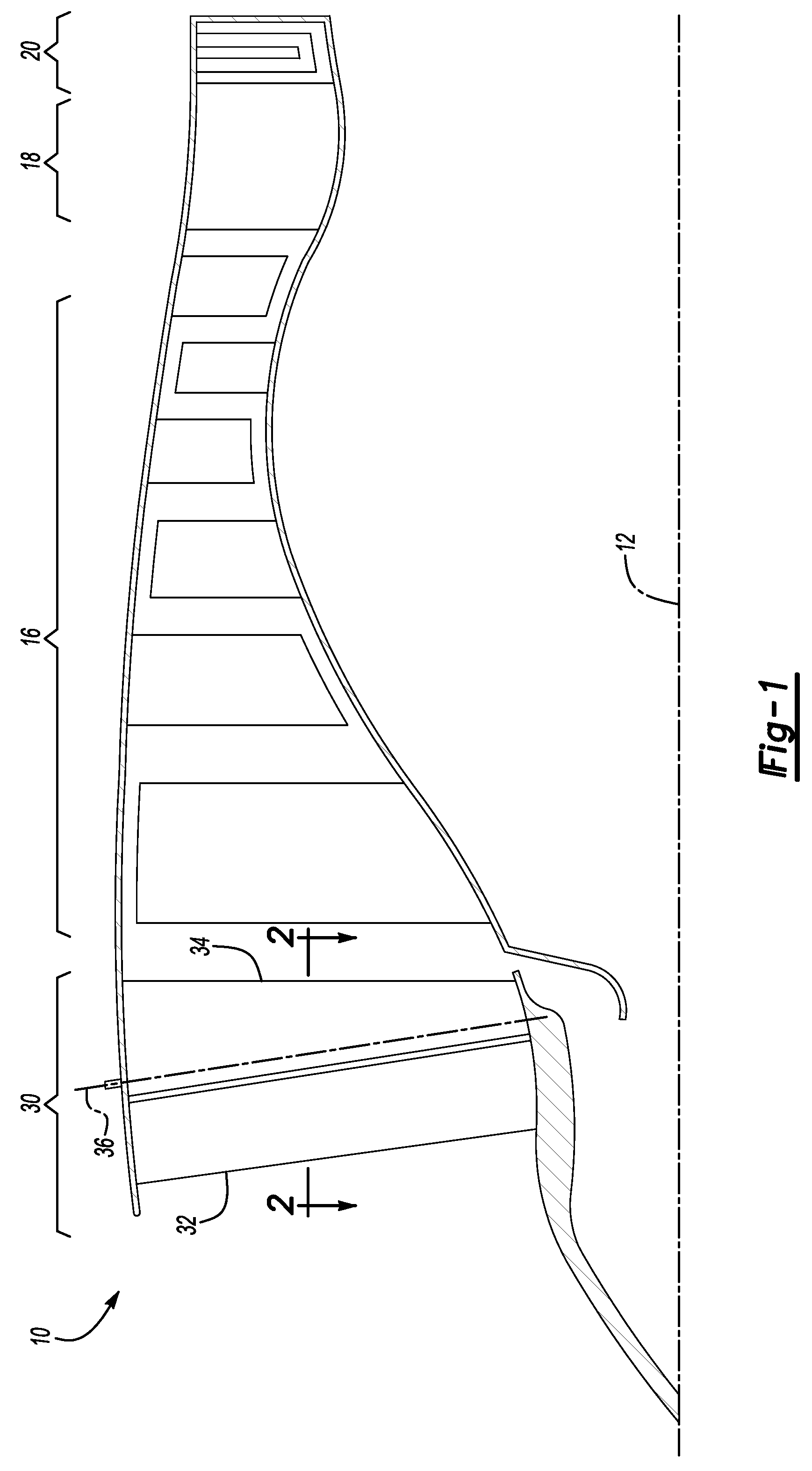
[0020]FIG. 1 shows a gas turbine engine 10 circumferentially disposed about an engine centerline or axial centerline axis 12. The engine 10 includes a compressor 16, a combustion section 18 and a turbine 20. As is well known, air compressed in the compressor 16 is mixed with fuel that is burned in the combustion section 18 and expands in the turbine 20. The turbine 20 rotates in response to the expansion driving the compressor 16.

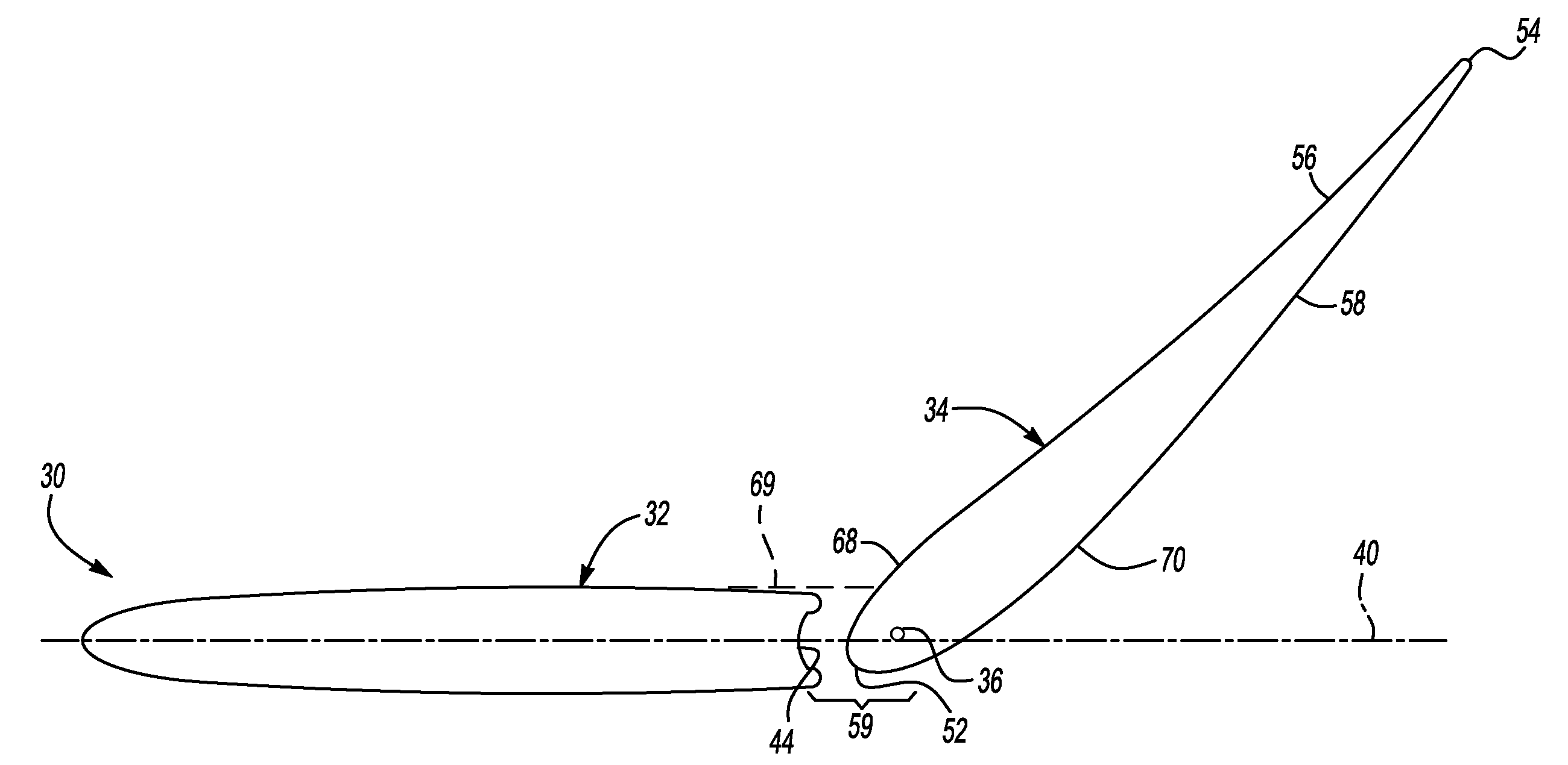
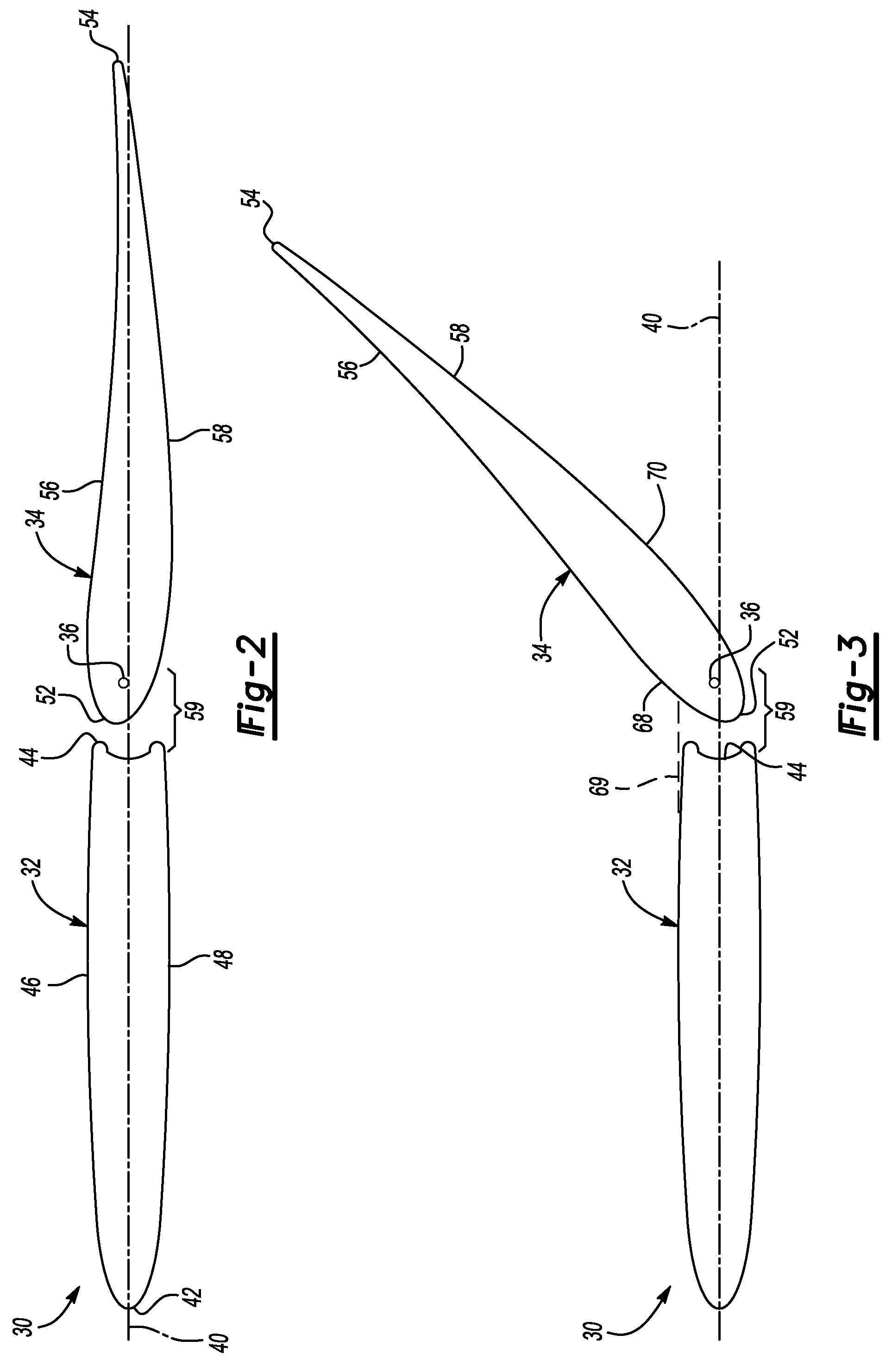
[0021]A plurality of inlet guide vanes 30 (one shown) are disposed about the centerline axis 12 in front of the compressor 16. Each in the inlet guide vanes 30 includes a strut 32 (a fixed airfoil) and a flap 34 (variable incidence airfoil). The flap 34 is pivotable about an axis 36 near the strut 32. Although the inlet guide vane 30 of the present invention is shown and used with a particular type of gas turbine engine 10, the invention is not so limited, and can be used with any known gas turbine engine type.

[0022]FIG. 2 is section view taken along line 2...


PUM


Abstract

An inlet guide vane provides improved, smooth airflow and avoids separation of flow even at high incidence angles. The inlet guide vane includes a strut having opposite side surfaces that are continuously curved to provide a controlled velocity distribution at the trailing edge of the strut. The inlet guide vane further includes a flap having a leading edge aligned behind the trailing edge of the strut. Generally, the strut and the flap are designed together so that low momentum air in the gap between the strut and the flap will be energized and entrained in the boundary layer of the flap. The airflow from the gap will remain attached to the flap to improve the flow from the flap.

Description

[0001]This invention was made with government support under contract number N00019-02-C3003 awarded by the United States Navy. The government has certain rights in this invention.BACKGROUND OF THE INVENTION[0002]The present invention relates generally to turbine engines and more particularly to a variable geometry inlet guide vane.[0003]Some gas turbine engines, particularly gas turbine engines for military aircraft, include variable geometry inlet guide vanes positioned in front of the compressor inlet or in front of the fan. The inlet guide vanes each include a fixed strut having a leading edge and a trailing edge. A flap is positioned with its leading edge behind the trailing edge of the strut. The flap is pivotable about an axis near its leading edge such that the flap is pivotable from a zero deflection position to a fully deflected position. In the zero deflection position, the leading edge and trailing edge of the flap are substantially aligned with and masked behind the lead...

Claims


Application Information

Patent Timeline
Patent Type & Authority Patents(United States)
IPC IPC(8): F01D17/12
CPCF01D5/148Y02T50/673F05D2240/12Y10S415/914Y02T50/60F04D29/30F04D29/24
Inventor CARROLL, CHRISTIAN A.ELEY, JAMES ALLENKLINETOB, CARL BRIAN
Owner RTX CORP
Why Eureka
Try Eureka