Electrical connector having improved terminal configuration

a terminal configuration and electric connector technology, applied in the direction of securing/insulating coupling contact members, fixed connections, coupling device connections, etc., to achieve the effect of reducing capacitance/impedance discontinuities, reducing size, and improving electrical performance and impedance levels

Active Publication Date: 2009-06-23
TYCO ELECTRONICS LOGISTICS AG (CH)
View PDF305 Cites 126 Cited by
  • Summary
  • Abstract
  • Description
  • Claims
  • Application Information

AI Technical Summary

Benefits of technology

[0005]In some embodiments of the present invention, the electrical terminals have a mounting end that is substantially smaller than the mating end, resulting in mechanical and electrical advantages. Moreover, unlike known electrical terminals, various embodiments of the terminals of the present invention also are configured to provide the mechanical and electrical characteristics necessary to function within an aperture of substantially reduced size, or a micro via. For example, the configuration of the mounting portion of certain embodiments of the present invention results in improved electrical performance and impedance levels, reduced capacitance / impedance discontinuities, reduced electrical degradation, reduced capacitive coupling, and / or reduced insertion forces in micro via applications, while maintaining the structural integrity necessary for high density electrical terminals and connectors.
[0007]In certain embodiments of the present invention, the electrical terminals of the connector are configured so that the insertion force associated with mounting the connector in a panel member is reduced, as compared with prior art connectors, and the insertion force is substantially constant over the length of travel of the mounting hardware in a panel member aperture. The electrical terminals of the present invention may have an end portion that facilitates insertion into and alignment with a panel member aperture by providing tactile feedback to a user.
[0008]Electrical connections with a panel member and electrical performance of the electrical connections between panel members and associated components may be improved by certain embodiments of the present invention. Some embodiments of the present invention also have the advantage that the mounting ends of the electrical terminals are configured to permit an increased number of electrical terminals per unit area (pin density) and to increase the possibilities for routing electrical traces between terminals.
[0009]In some embodiments of the present invention, a connector is provided for insertion into a panel member having apertures with a first diameter and apertures with a second diameter, where the first diameter is different from the second diameter. The dimensions of the electrical terminals to be inserted into the apertures may also vary from one terminal to the next within the connector. For example, a connector may include a first array of electrical terminals containing differential signal pairs separated by one or more grounds and a second array of electrical terminals containing differential signal pairs separated by one or more grounds, where the electrical terminals of the differential signal pairs have a first size and the ground terminals have a second size that is greater than the first size. The cross-talk between the differential signal pairs in adjacent linear arrays may be reduced by offsetting the differential signal pairs in one linear array from those of the adjacent linear array(s).

Problems solved by technology

Previous attempts to design such high speed electrical connectors have focused on the mating ends of the electrical terminals in the connector to achieve desired levels of impedance and cross-talk, pin densities, and other desired electrical and mechanical characteristics, but these attempts have largely ignored the mounting ends of the electrical terminals within the connector.

Method used


Image

  • Electrical connector having improved terminal configuration
  • Electrical connector having improved terminal configuration
  • Electrical connector having improved terminal configuration

Examples


Embodiment Construction

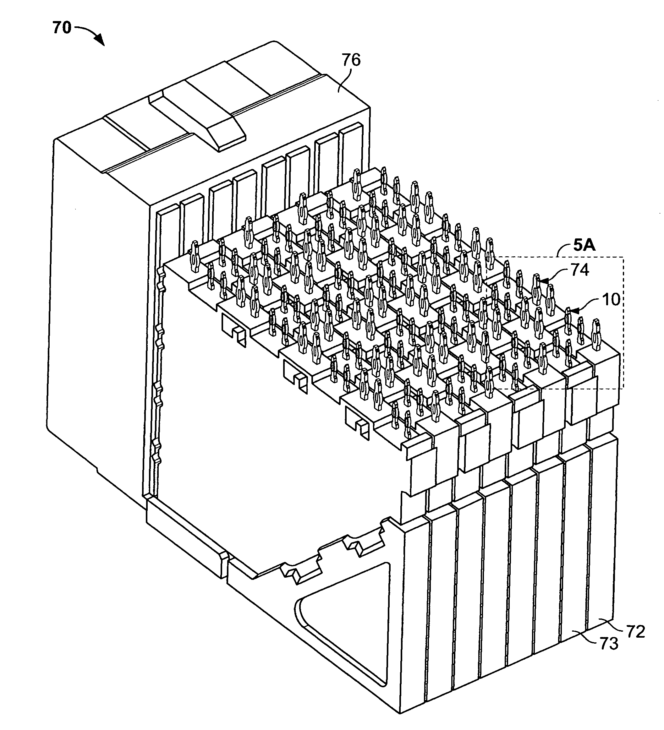
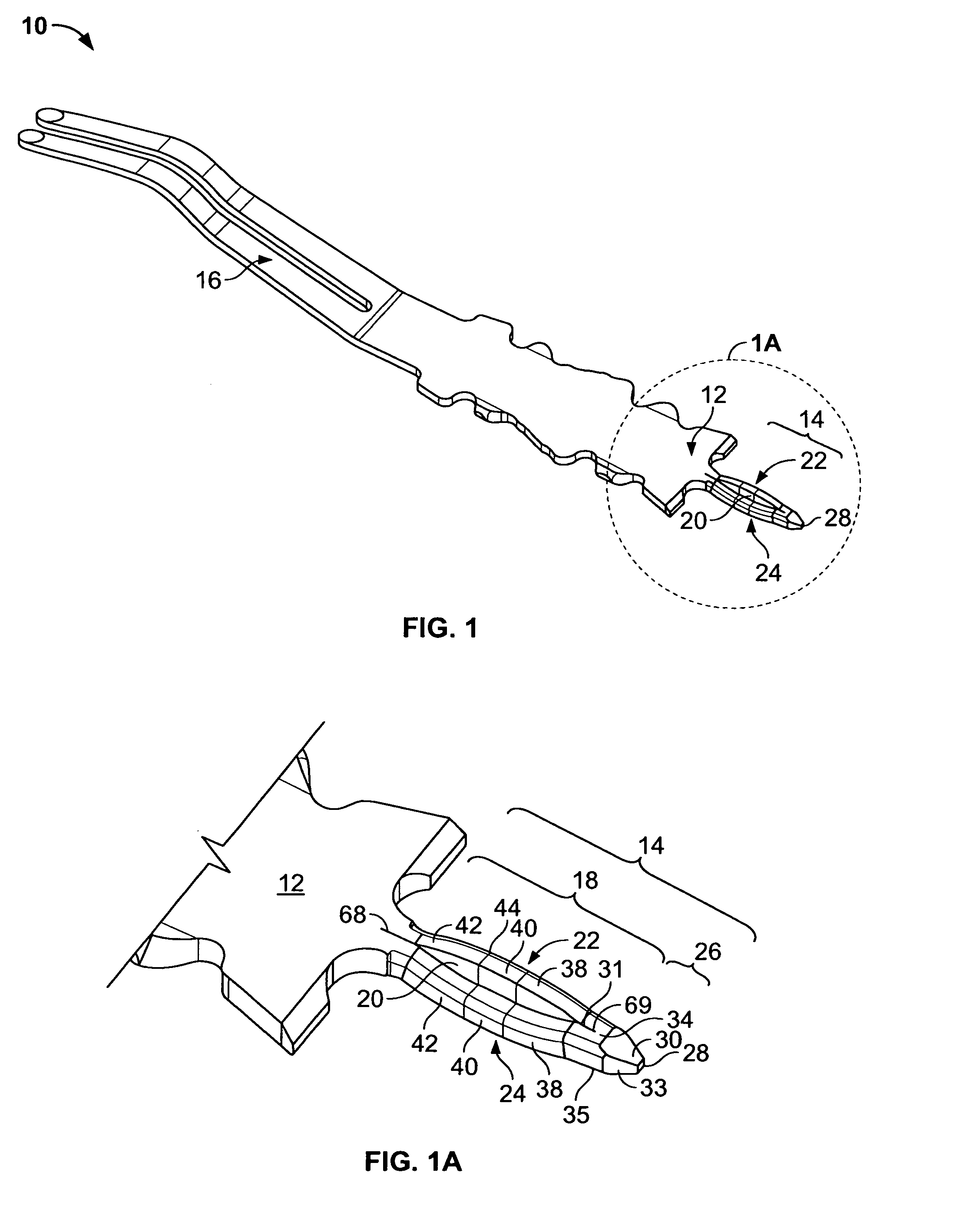
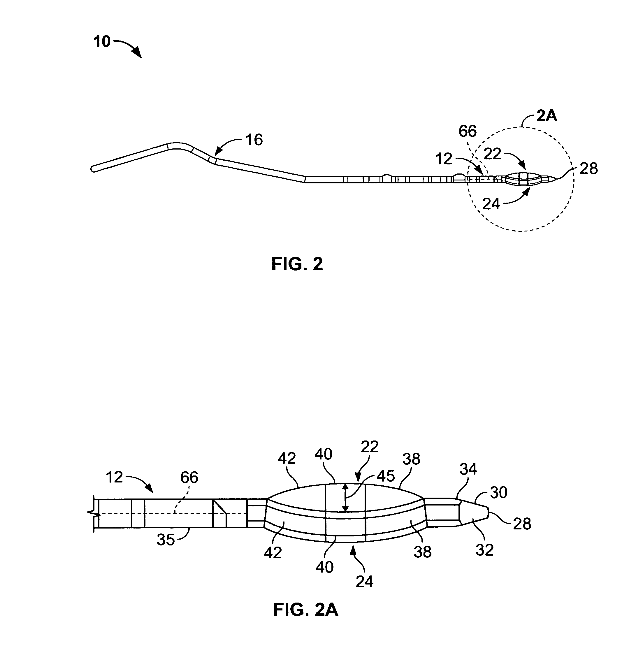
[0030]Various embodiments of the present invention include electrical terminals and electrical connectors having desirable electrical and mechanical characteristics, such as desirable impedance levels, impedance profiles, insertion losses, cross-talk levels, pin densities, and / or insertion force profiles, for example. In some embodiments, such desirable characteristics are achieved by an electrical terminal having a mounting end that is substantially smaller than its mating end. In other embodiments, an electrical connector, such as a press-fit connector, has a plurality of electrical terminals with mounting ends that are configured to provide improved characteristics. These and other embodiments are described in more detail below.

[0031]One embodiment of the present invention is directed to an electrical terminal 10, also referred to as a contact or pin, as depicted in FIGS. 1 to 3. In this embodiment, the electrical terminal 10 includes a base 12 with an insertion portion 14, or mo...


PUM


Abstract

An electrical terminal of the type to be inserted into an aperture of an electrical panel member is provided. The electrical terminal may include a base, an insertion portion extending from the base to a first end, a slit formed through the insertion portion and defining a compliant portion having a first leg and a second leg. Midpoints of each or both legs may be offset from the midpoint of the slit to achieve improved mechanical and electrical performance within a connector. Also provided is an electrical terminal having a tip that facilitates alignment with a panel member aperture and provides tactile feedback to a user, as well as an electrical terminal having a mounting end that is substantially smaller than its mating end, and connectors containing such terminals. Methods of routing electrical traces between adjacent electrical terminals are also provided.

Description

RELATED APPLICATIONS[0001]The present patent document is a continuation-in-part of application Ser. No. 11 / 462,012, filed Aug. 2, 2006, now U.S. Pat. No. 7,413,484, which is hereby incorporated by reference in its entirety.FIELD OF THE INVENTION[0002]The present invention relates to electrical terminals of the type to be inserted into apertures of an electrical panel member and electrical connectors containing such terminals.BACKGROUND OF THE INVENTION[0003]Due to the increasing complexity of electronic components, it is desirable to fit more components in less space on a circuit board or other substrate. Consequently, the spacing between electrical terminals within connectors has been reduced, while the number of electrical terminals housed in the connectors has increased, thereby increasing the need in the electrical arts for electrical connectors that are capable of handling higher and higher speeds and to do so with greater and greater pin densities. It is desirable for such con...

Claims


Application Information

Patent Timeline
Patent Type & Authority Patents(United States)
IPC IPC(8): H01R13/42H01R12/55
CPCH01R12/585H01R13/6471H01R13/6474H01R13/6587Y10S439/941
Inventor FEDDER, JAMES L.GLOVER, DOUGLAS W.HELSTER, DAVID W.MORGAN, CHAD W.ROTHERMEL, BRENTSHARF, ALEX M.TAYLOR, ATTALEE S.TROUT, DAVID A.
Owner TYCO ELECTRONICS LOGISTICS AG (CH)
Why Eureka
Try Eureka