Shift control apparatus and shift control method of automatic transmission of vehicle

a technology of automatic transmission and shift control, which is applied in the direction of electric control, gearing control, gearing elements, etc., can solve the problems of engine overspeed, lag between the operation of the accelerator pedal and the output of desired driving force, and the second downshift cannot be performed appropriately, so as to prevent overspeeding the engine

Inactive Publication Date: 2009-06-23
TOYOTA JIDOSHA KK
View PDF13 Cites 11 Cited by
  • Summary
  • Abstract
  • Description
  • Claims
  • Application Information

AI Technical Summary

Benefits of technology

[0007]It is an object of the invention to provide a shift control apparatus and shift control method for a vehicular automatic transmission that executes a torque reduction control during a second downshift operation in response to a second downshift determination that is made during a first downshift operation, for changing the rotational speed of the input member to a synchronous rotational speed quickly while preventing overspeeding of the engine. The desired driving force may be obtained quickly upon completion of the second downshift.
[0012]According to the aspect of the invention, the second downshift operation starts in response to the second downshift determination. Then the torque reduction control is kept in a stand-by state until the rotational speed of the input member becomes equal to or higher than the first determination speed, which is lower than the synchronous rotational speed. The torque of the power source allows the rotational speed of the input member to be increased quickly, and, when the rotational speed reaches the first determination speed, the torque reduction control is started. This makes it possible to obtain the desired driving force by performing the second downshift operation quickly while preventing overspeeding of the engine.
[0013]According to the aspect of the invention, the power source may be an engine with an electronically controlled throttle valve, which may be controlled to reduce the opening degree of the throttle valve so that the engine only outputs sufficient torque to increase the rotational speed of the input member to the synchronous rotational speed. This allows the engine torque to increase the rotational speed of the input member to the synchronous rotational speed further quickly while preventing the overspeeding of the engine, resulting in excellent shift response.
[0014]According to the aspect of the invention, the torque reduction control ends when the rotational speed of the input member exceeds the second determination speed, which is higher than the synchronous rotational speed, and then decreases to be lower than the third determination speed, and the rotational speed of the input member decreases for a predetermined period. This makes it possible to start generating the torque quickly upon completion of the second downshift while preventing overspeeding the engine when the torque reduction control ends. Especially, the torque reduction control termination condition is set to be established when the rotational speed of the input member is decreasing for a predetermined period. This may prevent the accidental termination of the torque reduction control owing to noise caused by the fluctuation of the rotation, thus further preventing the overspeeding of the engine.
[0015]According to the aspect of the invention, if the torque reduction control termination condition is not been established over a predetermined time or longer, the torque reduction control is ended. This makes it possible to prevent the reduced torque operation of the power source from continuing for an extended time due to the abnormality during the second downshift to end the downshift even if the torque reduction control termination condition is not satisfied.

Problems solved by technology

Accordingly, the engine may overspeed, and the second downshift cannot be performed appropriately.
This also results in a time lag between operation of the accelerator pedal operation and output of desired driving force.

Method used


Image

  • Shift control apparatus and shift control method of automatic transmission of vehicle
  • Shift control apparatus and shift control method of automatic transmission of vehicle
  • Shift control apparatus and shift control method of automatic transmission of vehicle

Examples


Embodiment Construction

[0035]An embodiment of the invention will be described referring to the drawings.

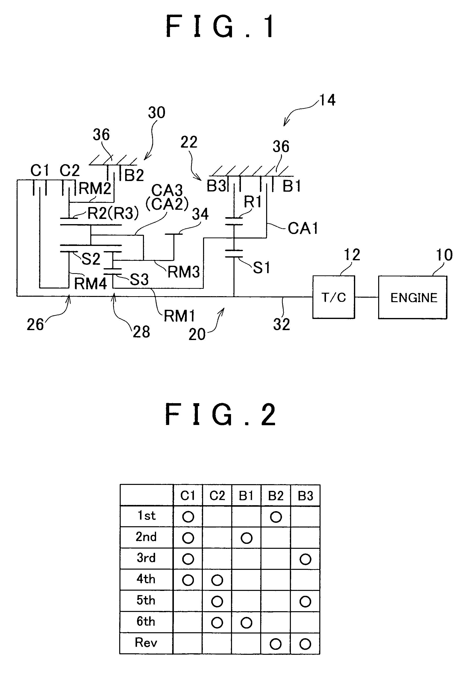
[0036]FIG. 1 shows an outline of a drive unit for an FF (Front engine, Front drive) vehicle in which the engine is transversely mounted. The output of the internal combustion engine 10, for example, such as a gasoline engine, is transferred from a differential gear unit (not shown) to the front wheels via a torque converter 12, and an automatic transmission 14. The engine 10 is employed as the power source for driving the vehicle, and the torque converter 12 is employed as a fluid coupling.

[0037]The automatic transmission 14 includes a first shift portion 22, mainly formed of a first planetary gear unit 20 of single pinion type, and a second shift portion 30, mainly formed of a second planetary gear unit 26 of single pinion type, and a third planetary gear unit 28, of double pinion type coaxially arranged such that the rotation of an input shaft 32 is shifted to be output from an output gear 34. The inp...


PUM


Abstract

The invention relates to a shift control apparatus for an automatic transmission, that executes a torque reduction control when the transmission executes a second downshift in response to a second downshift determination made during first downshift. The shift control apparatus includes a multiple shift execution unit that starts the second downshift operation in response to the second downshift determination, and a torque reduction control execution unit that executes a torque reduction control when the rotational speed of the input member is increased to at least a predetermined first determination speed, which is determined in accordance with a shift ratio of a gear stage after the second downshift operation, after the second downshift starts. This allows the rotational speed of the input shaft to be quickly changed to the appropriate synchronous rotational speed. Thus, the desired driving force is provided upon completion of the second downshift without overspeeding the engine.

Description

[0001]The disclosure of Japanese Patent Application No. 2005-247859, filed on Aug. 29, 2005, including the specification, drawings and abstract, is incorporated herein by reference in its entirety.BACKGROUND OF THE INVENTION[0002]1. Field of the Invention[0003]The invention relates to a shift control apparatus and shift control method for an automatic transmission, which executes a torque reduction control when downshifting in response to a second downshift determination made during a first downshift.[0004]2. Description of Related Art[0005]Japanese Patent Publication Laid-Open No. 10-281277 describes a shift control for an automatic transmission that executes a shifting of a rotation transferred from an engine to an input member so as to be output to drive wheels. During a first downshift, in which a first friction coupling device is engaged, the operation of the accelerator by the driver may cause a second downshift command to be output. When the transmission executes the second d...

Claims


Application Information

Patent Timeline
Patent Type & Authority Patents(United States)
IPC IPC(8): B60W10/06B60W10/10F02D29/00F02D41/04F16H59/24F16H59/42F16H61/08F16H61/68F16H61/684F16H63/50
CPCB60W10/06B60W10/115B60W30/19F16H63/502F16H61/08F16H61/686Y10T477/677F16H2306/14F16H2306/24F16H2061/0477Y10T477/675F16H61/04F16H59/68F16H61/00
Inventor AYABE, ATSUSHISAGAWA, AYUMUSUGIMURA, TOSHIOSUZUKI, TOSHINARIISHIHARA, HISASHI
Owner TOYOTA JIDOSHA KK
Why Eureka
Try Eureka