Flood barrier system

a technology of flood barrier and sluice plate, which is applied in the direction of shutter/movable grille, manufacturing tools, construction fastening devices, etc., can solve the problems of large damage, inundation of the entire structure, and floodwater occasionally in homes, offices, and factories, etc., and achieves the effect of quick and easy removal

Active Publication Date: 2009-06-30
PRESRAY
View PDF2 Cites 17 Cited by
  • Summary
  • Abstract
  • Description
  • Claims
  • Application Information

AI Technical Summary

Benefits of technology

[0004]The present invention deals with improvements in flood barrier systems of otherwise generally known types to enable them to be installed easily and quickly with minimum personnel, such that the time requirements for making a flood barrier system ready are greatly minimized, providing greater assurance that a structure can be fully protected at all low level openings in a minimum time period. In the flood barrier system of the invention, a plurality of horizontally disposed barrier elements are stacked one on top of the other to form a barrier of the desired height. But instead of bolting each barrier element to its neighbor below, the entire series of barrier elements is stacked in place against the front face of the wall structure surrounding the opening to be protected, and the individual barrier elements are initially held snugly against the front face by means of end clamps engageable with the opposite ends of the barrier elements.
[0006]With this structure and new installation procedure, a flood barrier may be installed and made ready in a fraction of the time heretofore required, providing greater assurance that all of the necessary barrier systems may be installed and made ready in advance of the rising flood waters.
[0007]To advantage, the clamping mechanisms utilized preferentially in the new system are in the nature pipe-mounted clamps, which are carried by vertical pipe sections mounted at the top of the barrier system. Such clamping arrangements incorporate screw-threaded clamping members of relatively limited range of vertical movement which are carried by clamp bodies slideable vertically over the length of the pipe sections on which they are mounted. Vertical sliding movement of the clamp bodies, when not under load, is easily accomplished, so that the clamp bodies may be raised out of the way during initial installation of the barrier elements. When the last barrier element is installed, the clamp bodies can be slid downward along their carrier pipes until the threaded clamping members engage the upper surface of the uppermost barrier element. As soon, as clamping pressure is applied by the screw elements, the clamp bodies lock in position on the carrier pipes, and significant downward pressure can be applied to the entire stack of the barrier elements to assure the necessary sealing effectiveness between barrier elements.
[0008]In the system of the invention, when the flood waters have receded, the barrier elements are removed and stored in an accessible location. The vertically acting pressure clamps, and the horizontally acting end clamps that engage the ends of the barrier elements can be left in place on the wall structure surrounding the opening. A shroud arrangement is provided that is secured over the vertically acting pressure clamps and the end clamps over the entire vertical extent thereof such that all of these elements are concealed from view and protected against being struck by people or equipment. The shrouds can be installed with just a few bolts so as to be quickly and easily removable when the time comes to re-install the flood barrier.

Problems solved by technology

In certain areas, homes, offices and commercial and factory buildings occasionally are inundated by flood waters.
In this respect, water flowing in through a single unprotected opening, even though others are protected, can inundate the entire structure and cause great damage.

Method used


Image

  • Flood barrier system
  • Flood barrier system
  • Flood barrier system

Examples


Embodiment Construction

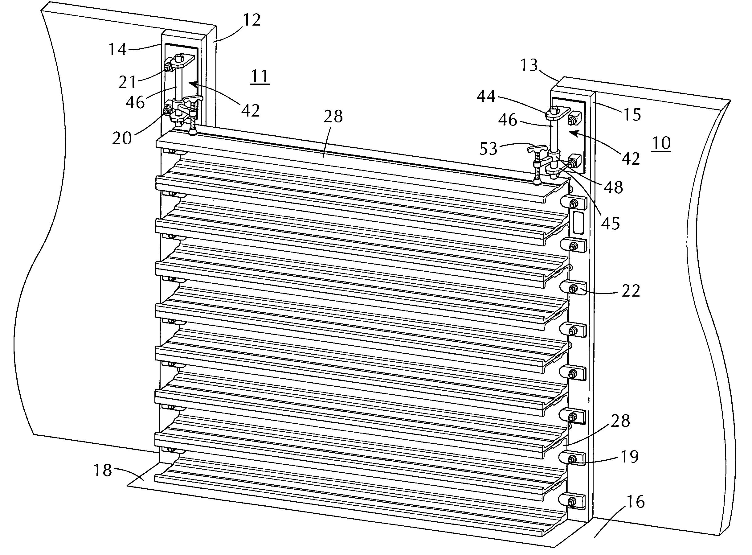
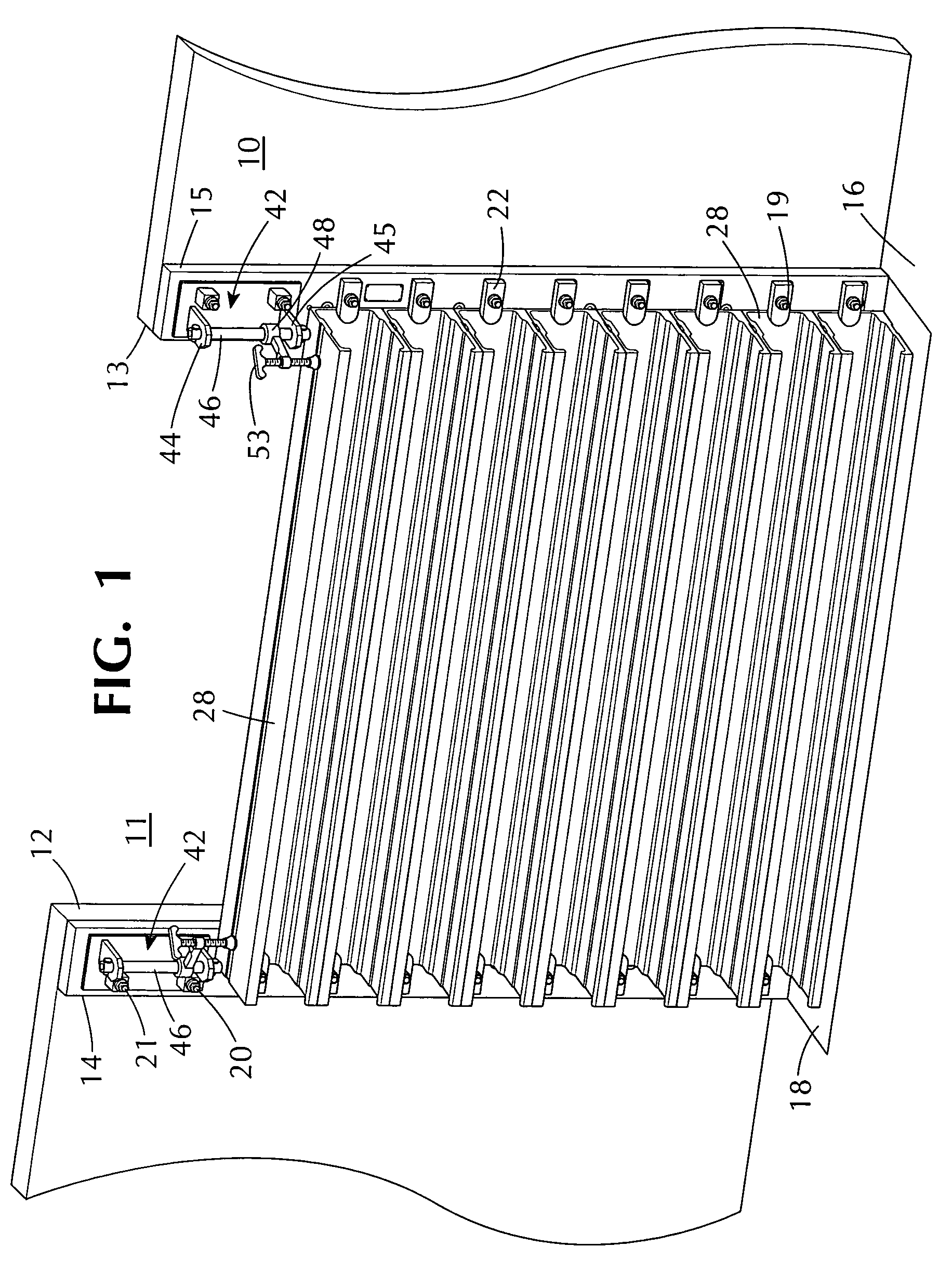
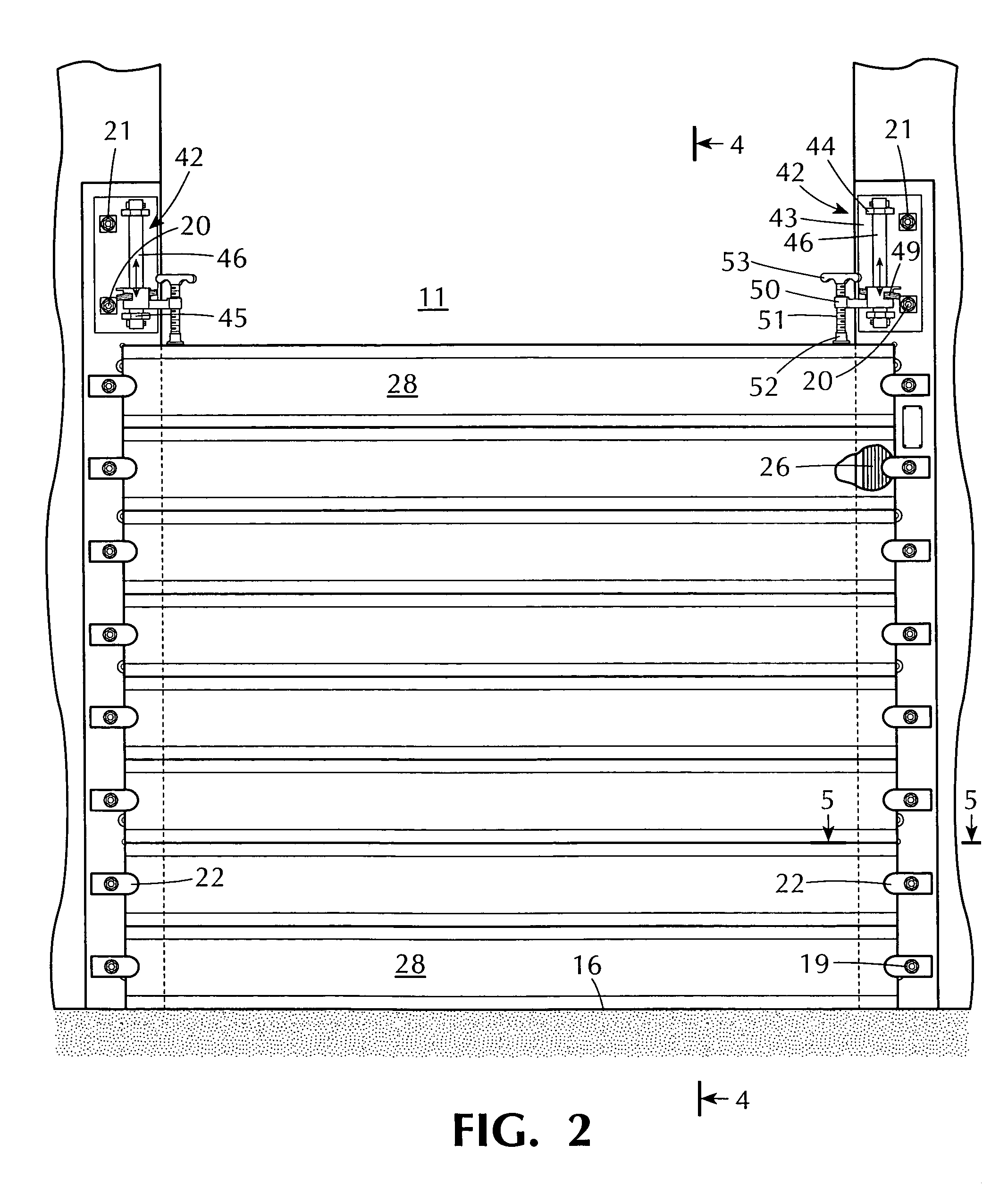
[0017]Referring now to the drawings, the reference numeral 10 designates generally a wall structure of a typical commercial building, for example, having an opening 11 therein. In the illustrated example, the opening 11 is intended to represent a typical doorway. The upper portion of the wall structure 10 and the opening 11 is omitted from the illustration as it plays no part in the description of the invention. Along each side 12, 13 of the opening 11 there are vertically disposed sealing plates 14, 15 which extend from ground level (shown at 16) for a suitable vertical distance for dealing with expected flooding levels in the region. Typically, for an opening 11 of significant height, such as a doorway, a flood barrier need not extend for the full height of the opening and, in the illustrated embodiment of the invention, the sealing plates 14, 15 may extend upward for a distance of around five feet, suitable for constructing a flood barrier of about four feet in height. The sealin...


PUM

PropertyMeasurementUnit
heightaaaaaaaaaa
heightaaaaaaaaaa
widthaaaaaaaaaa

Abstract

A flood barrier system for sealing an opening in a wall structure against the inflow of flood waters. The system comprises a plurality of elongated, horizontally disposed barrier elements of a length somewhat greater than the width of the opening. The barrier elements are stacked vertically, one upon the other against the outer face of the wall structure. End clamps engage opposite ends of the individual barrier elements to press them snugly against the outer surface of the wall, providing seals along the opposite vertical side edges of the opening. A simplified clamping mechanism is provided above the uppermost barrier element, with provisions to apply vertically downward clamping pressure on the uppermost barrier element, and thus upon the entire series of vertically stacked barrier elements. Each of the barrier elements has a resilient seal along its lower surface, engageable with an upper surface of the neighboring barrier element below such that, when the stack of barrier elements is under clamping pressure from above, effective water seals are provided between each of the barrier elements. An important benefit and advantage of the arrangement is the facility and thickness with which an effective flood barrier may be installed when flooding conditions are imminent.

Description

BACKGROUND OF INVENTION[0001]In certain areas, homes, offices and commercial and factory buildings occasionally are inundated by flood waters. In order to minimize damage from rising flood waters, such structures can utilize flood barriers that are installed in low level doors and windows to seal the openings against inflow of water into the structure as the water level reaches and exceeds the level of the window or door openings. Various barrier systems are available for this purpose, with a wide variety of design features dictated to a considerable extent by the size of the opening to be protected.[0002]For the protection of a relatively wide doorway, for example, against flood waters that may rise to a considerable level above the bottom of the door opening, the barrier system must have considerable structural soundness in order to effectively resist the pressure of water across a wide area and at a relatively high level. One such system that is effective for the purpose has been...

Claims


Application Information

Patent Timeline
Patent Type & Authority Patents(United States)
IPC IPC(8): E06B3/26
CPCE06B9/02Y10T29/53961E06B2009/007
Inventor SMITH, JASON W.
Owner PRESRAY
Why Eureka
Try Eureka