Twin spool turbine engine with power take-off means on the low-pressure and high-pressure rotors, and power take-off module for the turbine engine

Active Publication Date: 2009-06-30
SN DETUDE & DE CONSTR DE MOTEURS DAVIATION S N E C M A
View PDF9 Cites 73 Cited by
  • Summary
  • Abstract
  • Description
  • Claims
  • Application Information

AI Technical Summary

Benefits of technology

[0012]Modern turbine engines do not have such amounts of space for the power take-off from the rotors at the ends of the transmission shafts. Furthermore, present-day turbine engines are designed for a power take-off from the HP rotor only and it would be desirable to propose a power take-off and transmission device for the LP and HP rotors which could be installed without significant changes to the structure of the turbine engine. It is also necessary, in the case of the pinions sec

Problems solved by technology

Modern turbine engines do not have such amounts of space for the po

Method used


Image

  • Twin spool turbine engine with power take-off means on the low-pressure and high-pressure rotors, and power take-off module for the turbine engine
  • Twin spool turbine engine with power take-off means on the low-pressure and high-pressure rotors, and power take-off module for the turbine engine

Examples


Example

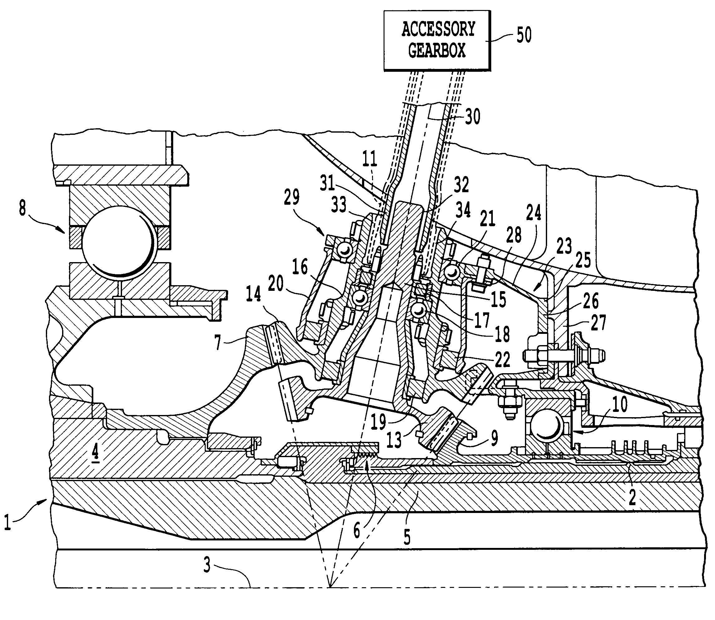
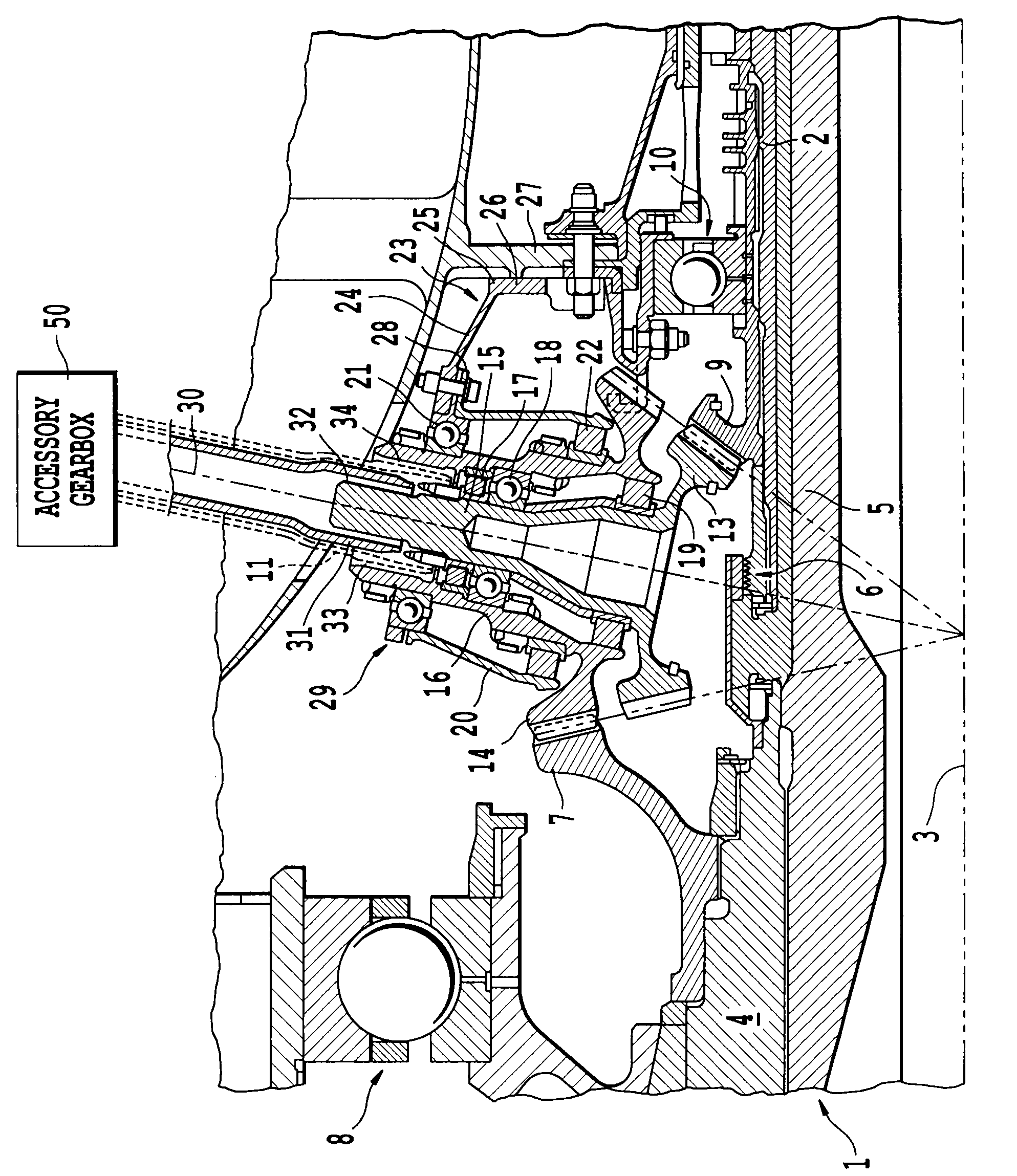
[0022]The turbine engine of the invention is a twin spool turbine engine comprising a low-pressure (LP) rotor 1 and a high-pressure (HP) rotor 2, which are mounted to rotate about the axis 3 of the turbine engine. This type of turbine engine is well known to those skilled in the art. It may be a jet engine or a turboprop engine, for example. In fact it is any turbine engine comprising a compressor and a turbine, of the twin spool type, having a low-pressure spool and a high-pressure spool. Internal and external or inside and outside is to be understood in the description to be internal or external, or inside or outside pertaining to the turbine engine, in the radial direction, with respect to its axis 3.

[0023]More specifically, the turbine engine functionally comprises, from the upstream to the downstream end in the direction in which the gases flow, a fan, a compressor, a combustion engine, a turbine and a jet pipe. As it is a twin spool engine it comprises an LP compressor upstrea...


PUM


Abstract

The invention relates to a twin spool turbine engine comprising a high-pressure rotor and a low-pressure rotor, at least one accessory gearbox, a drive means, driving coaxial transmission shafts that transmit movement to the accessory gearbox, characterized in that the drive means comprises a high-pressure drive pinion secured to the high-pressure rotor near its upstream end, a low-pressure drive pinion secured to the low-pressure rotor upstream of the high-pressure rotor, and a power take-off module in direct mesh with the drive pinions, driving the transmission shafts.
By virtue of the invention, the transmission shafts run coaxial with one another and therefore pass through a single arm. The use of a power take-off module simplifies the mechanism. The turbine engine is simpler to assemble.

Description

BACKGROUND OF THE INVENTION[0001]1. Field of the Invention[0002]The invention relates to a twin spool turbine engine with power take-off means on the low-pressure and high-pressure rotors, to a power take-off module for the turbine engine and to a method for assembling the turbine engine.[0003]2. Discussion of Background[0004]Some of the power generated by an aeronautical turbine engine is used to power various components, both of the turbine engine and also of the aircraft to the propulsion of which the turbine engine contributes.[0005]Some of this power is actually tapped off the high-pressure (HP) compressor, the compressed air of which is used in particular to pressurize and air-condition the cabin of the aircraft, or for de-icing purposes. Some more of this power is tapped mechanically off the shaft of the HP stage of the turbine engine, to drive the input shaft of an accessory gearbox positioned on a casing of the turbine engine. This input shaft is rotationally driven by a tr...

Claims


Application Information

Patent Timeline
IPC IPC(8): F02C7/32
CPCF02C7/32Y02T50/671F05D2230/61Y02T50/60
Inventor BART, JACQUES RENEBEUTIN, BRUNO ALBERTMOREL, PATRICK CHARLES GEORGES
Owner SN DETUDE & DE CONSTR DE MOTEURS DAVIATION S N E C M A
Why Eureka
Try Eureka