Solenoid drive apparatus

a solenoid drive and solenoid technology, applied in the direction of valve operating means/release devices, machines/engines, magnetic bodies, etc., can solve the problems of a failure to meet the requirements of the application

Active Publication Date: 2009-06-30
DENSO CORP
View PDF18 Cites 7 Cited by
  • Summary
  • Abstract
  • Description
  • Claims
  • Application Information

AI Technical Summary

Problems solved by technology

However, the conventional solenoid drive apparatus has suffered from a degradation of a magnetic property (attractive force, responsibility) because of a magnetic block caused by the rubber sealing member 100, which is non-magnetic and has a large thickness.
Further, there has been a fear of fault sealing because the sealing member 100 sometimes sticks out of the receiving groove 29 when the coil 2 is assembled to the body 1 or the plate 3.
Further, there has been a fear of another fault sealing because a surface of the sealing member 100 is worn due to a friction of the sealing member 100 with the body 1 or the plate 3 when the coil 2 is assembled to the body 1 or the plate 3.

Method used


Image

  • Solenoid drive apparatus
  • Solenoid drive apparatus
  • Solenoid drive apparatus

Examples


first embodiment

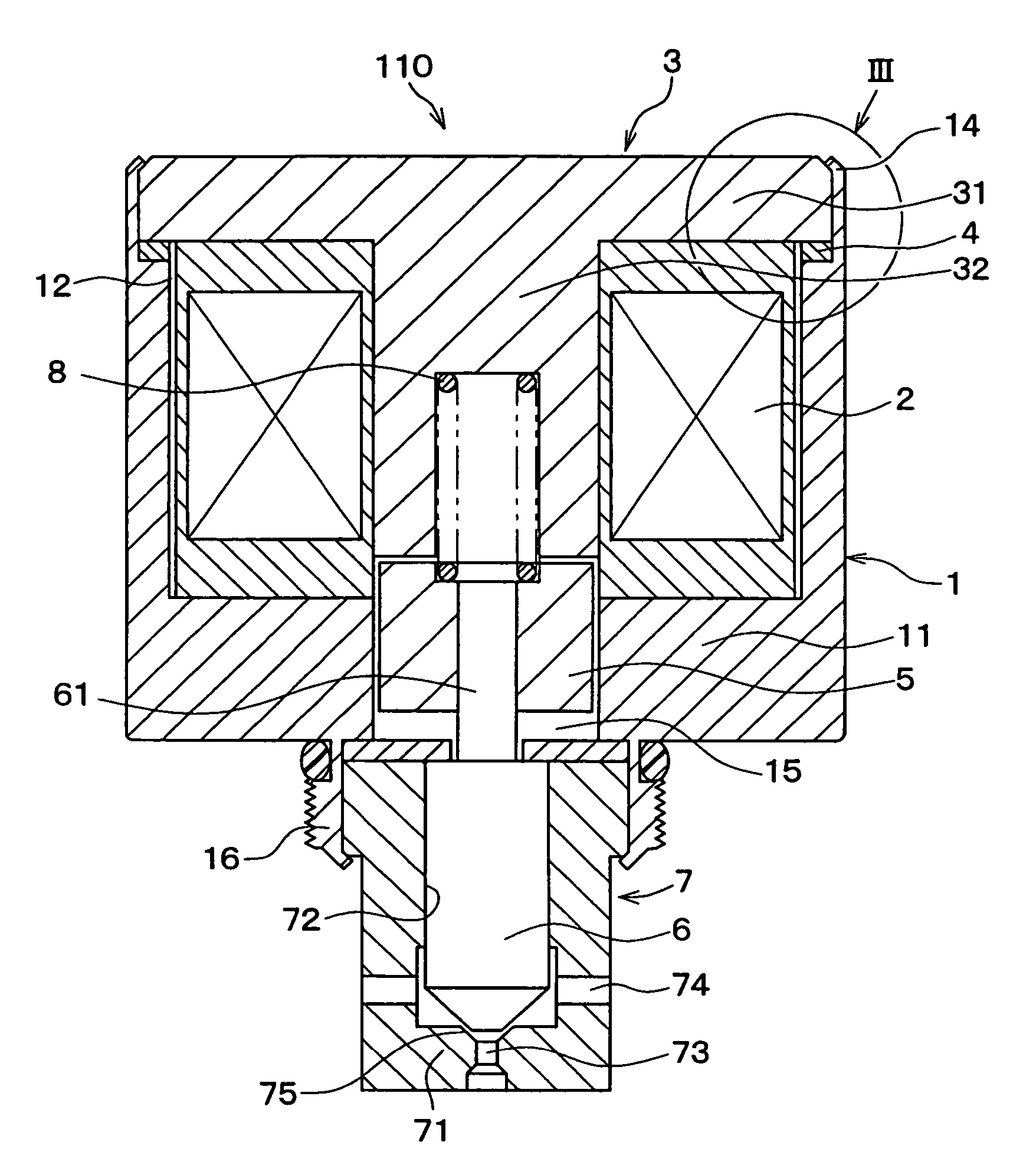
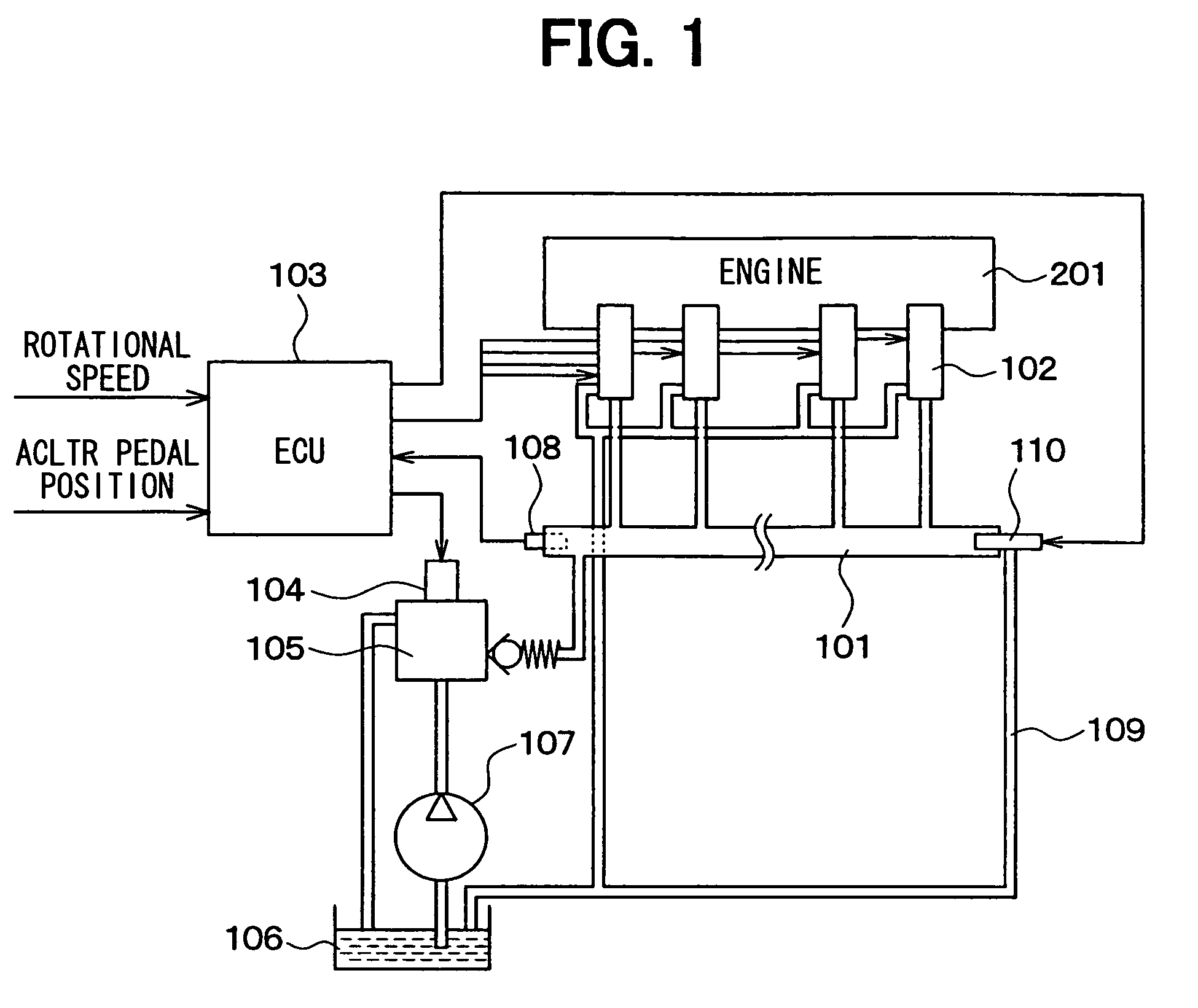
[0016]As shown in FIG. 1, a common rail fuel injection system having a solenoid drive apparatus of a first embodiment includes an accumulator 101, a diesel engine (internal combustion engine) 201, multiple injection valves 102, and an electronic control unit (ECU) 103. The accumulator 101 accumulates high-pressure fuel. The accumulator 101 is connected with each of the injection valves 102, which is provided to a corresponding one of cylinders of the internal combustion engine 201. Thus, the high-pressure fuel accumulated in the accumulator 101 is injected into the corresponding cylinder through each injection valve 102. The ECU 103 controls open timing and a valve open period of the injection valve 102.

[0017]The ECU 103 includes a known microcomputer, which has a CPU, a ROM, and RAM, and is not shown. The microcomputer in turn executes various processes stored in the microcomputer. The ECU 103 receives information, such as an engine rotational speed and a depressing amount (a pedal...

second embodiment

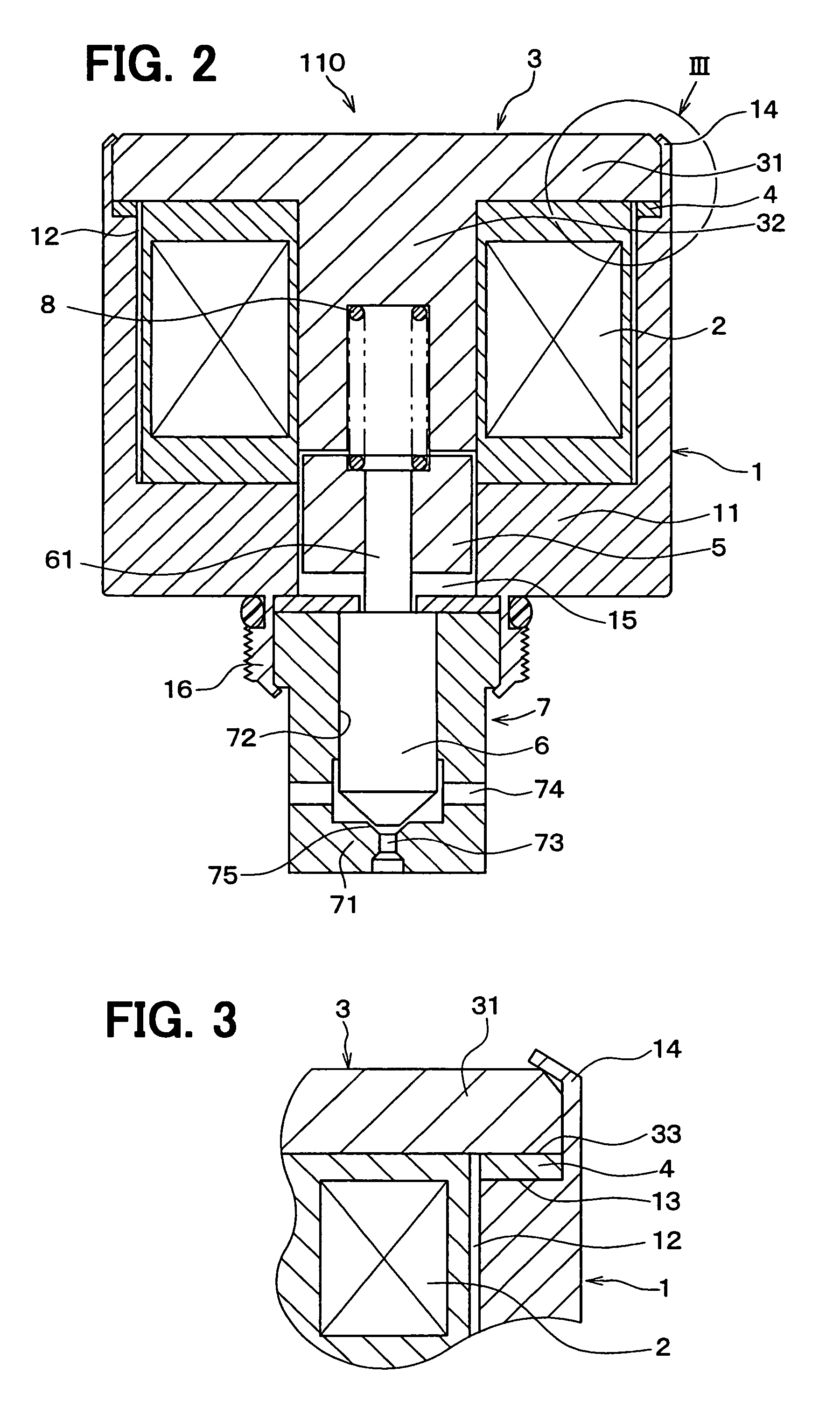
[0036]A second embodiment of the present invention will be described. FIG. 4 is a sectional view showing a structure of a gasket for a solenoid drive apparatus according to the second embodiment of the present invention. Similar components of the solenoid drive apparatus of the present embodiment, which are similar to the components of the solenoid drive apparatus of the first embodiment, will be indicated by the same numerals.

[0037]As shown in FIG. 4, in the present embodiment, flat annular elastic members 9 are joined to opposite surfaces (sides) of the flat annular gasket 4, which is magnetic metal. In other words, one of the elastic members 9 is attached to one face of the gasket 4, the one face facing the body end surface 13 (see FIG. 3). Also, the other of the elastic members 9 is attached to an opposite face of the gasket 4, the opposite face facing the plate end surface 33 (see FIG. 3). Here, hardness of the elastic members 9 is lower than that of the gasket 4.

[0038]In the p...


PUM


Abstract

A solenoid drive apparatus for driving a driven member by a magnetic attractive force includes a tubular magnetic metallic body, a coil, a magnetic metallic plate, and a magnetic gasket. The tubular magnetic metallic body has an opening portion at one end. The coil is received in the body from the opening portion and provides a magnetic field when the coil is energized. The magnetic metallic plate closes the opening portion of the body. The magnetic gasket is held between the body and the plate.

Description

CROSS REFERENCE TO RELATED APPLICATION[0001]This application is based on and incorporates herein by reference Japanese Patent Application No. 2005-268532 filed on Sep. 15, 2005.BACKGROUND OF THE INVENTION[0002]1. Field of the Invention[0003]The present invention relates to a solenoid drive apparatus that generates a magnetic force when the apparatus is energized.[0004]2. Description of Related Art[0005]A conventional solenoid drive apparatus includes a magnetic metallic body 1, a coil 2 and a metallic plate 3, as shown in FIG. 5. The body 1 houses the coil 2 and an opening portion of the body 1 is closed by the plate 3. The solenoid drive apparatus further includes a rubber sealing member 100, such as an O-ring, in order to limit water from entering from an exterior (see e.g., Japanese Unexamined Patent Publication No. 2001-182638). Here, the rubber sealing member 100 usually has a thickness of 1.5 mm or more.[0006]However, the conventional solenoid drive apparatus has suffered from...

Claims


Application Information

Patent Timeline
Patent Type & Authority Patents(United States)
IPC IPC(8): F16K31/02
CPCF02M63/0015F02M63/0019F02M63/0031F02M63/0225F02M63/025F16K31/0675H01F7/128H01F7/1607F02M2200/08
Inventor MITSUMATA, NAOKIMURAKAMI, FUMIAKI
Owner DENSO CORP
Why Eureka
Try Eureka