Device for measuring the motion of a conducting body through magnetic induction

a technology of magnetic induction and moving body, which is applied in the direction of acceleration measurement using interia forces, galvano-magnetic hall-effect devices, instruments, etc., can solve the problems of falsification of measurement, increase in heating effect, and limit the application of conventional inductive motion sensors for measuring rotation speed, so as to reduce thermal noise, effectively cool, and reduce heat produced by eddy current losses

Inactive Publication Date: 2005-02-01
SIEMENS AG
View PDF13 Cites 145 Cited by
  • Summary
  • Abstract
  • Description
  • Claims
  • Application Information

AI Technical Summary

Benefits of technology

The magnetic field generating means and/or the measuring device(s) and/or the corresponding flux conducting means are preferably secured to a common support or several associated supports or support elements, in particular an angled sheet metal support, an

Problems solved by technology

One problem with the inductive motion sensor described in DE 37 30 841 A1 is heating of the moving body by Joule heating due to the induced eddy currents, with the heating effect increasing with increasing rotation speed and/or speed of the moving body.
This limits the application of the conventional inductive motion sensor for measuring the rotation speed and/or speed for two reasons.
On the other hand, even small temperature changes can falsify the measurement result.
In particular, temperature variations cause a drift of the DC magnetic field of the permanent magnets, an additional th

Method used


Image

  • Device for measuring the motion of a conducting body through magnetic induction
  • Device for measuring the motion of a conducting body through magnetic induction
  • Device for measuring the motion of a conducting body through magnetic induction

Examples


Embodiment Construction

Identical parts and quantities are indicated in FIGS. 1 to 6 with the same reference numerals.

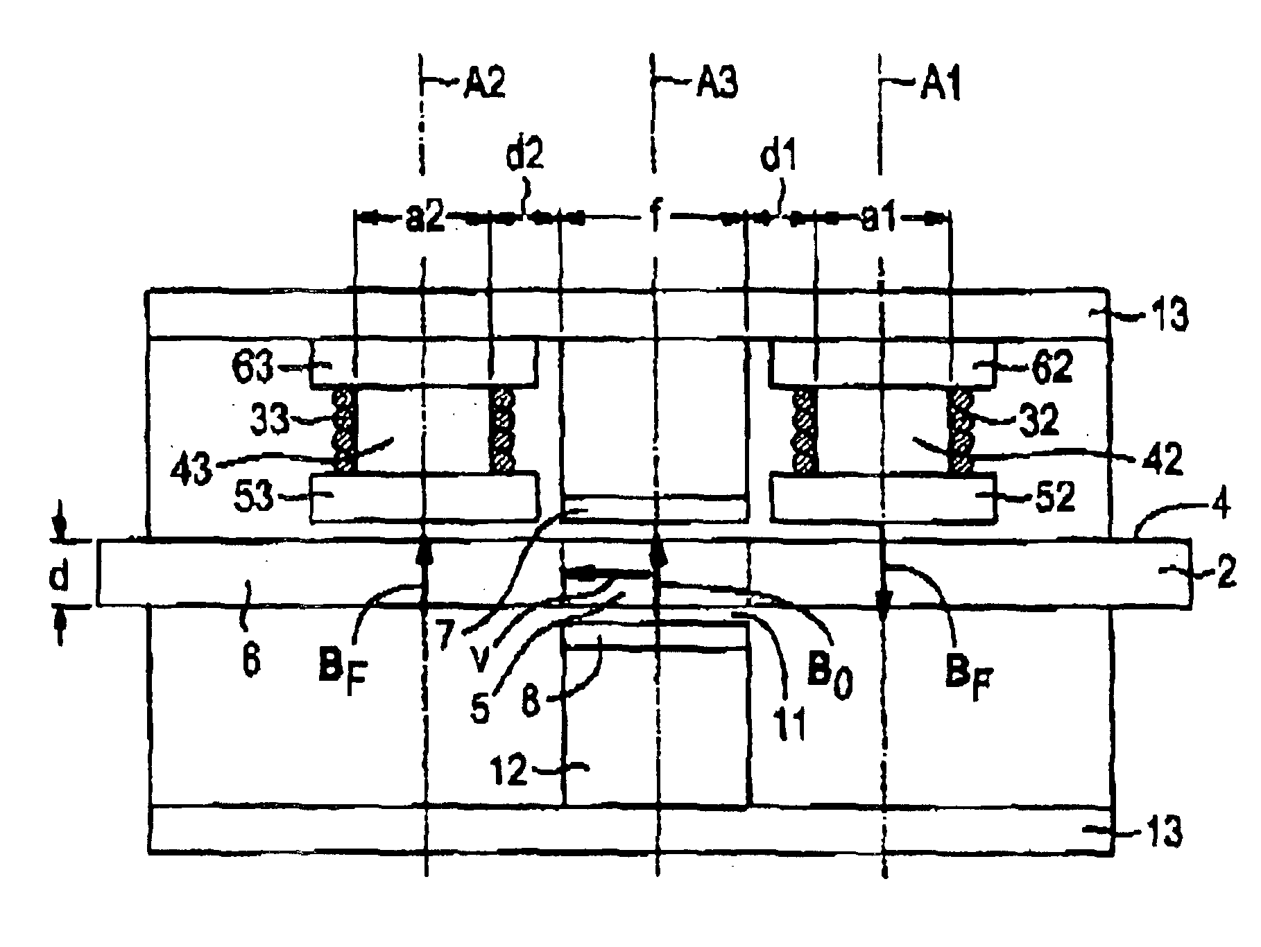
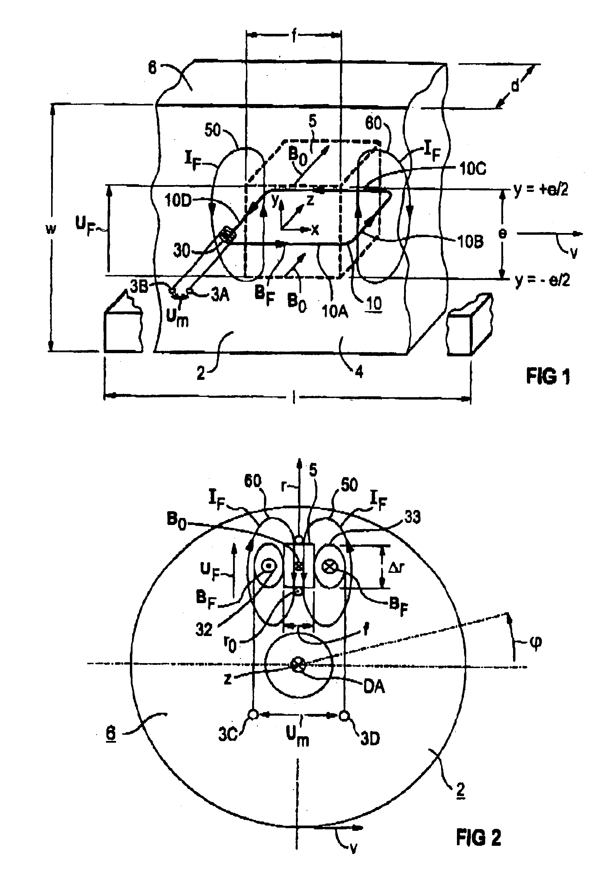
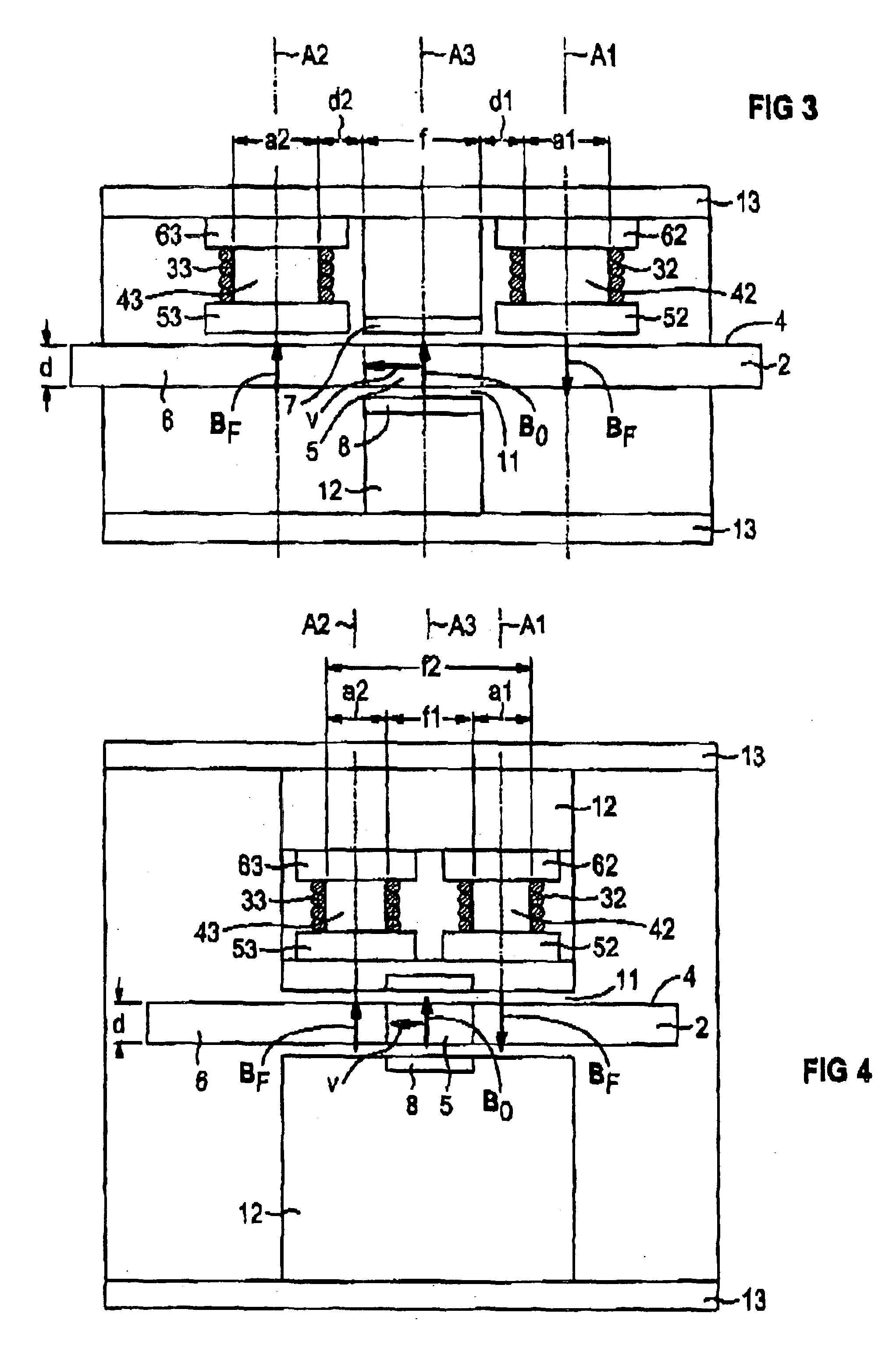
A moving body whose motion is to be measured is indicated in FIGS. 1 to 6 with the reference numeral 2. The illustrated moving bodies 2 are in all embodiments made of an electrically conducting material, in particular, without limitations, of a metal such as copper (Cu) or aluminum (Al) or a metal alloy, such as steel.

In the embodiment according to FIG. 1, the moving body 2 moves in a Cartesian x-y-z-coordinate system with a vector velocity v in a straight line in the x-direction in the direction of the arrow. The moving body 2 is penetrated in a spatially limited, for example cuboid-shaped partial area 5 by a time-independent (or DC) magnetic field B0 which extends in the z-direction and is perpendicular to the velocity vector v and perpendicular to a substantially flat surface 4 of the moving body 2. An outer partial area 6 surrounding the partial area 5 of the moving body 2 is free of th...


PUM


Abstract

A device for measuring a motion of a moving electrically conducting body is disclosed. A magnetic field generated by, for example, electromagnets or permanent magnets, penetrates at least a partial area of the moving body. Two or more measuring devices are arranged outside the magnetic field to measure a measurement magnetic field that is induced by electrical currents in the moving body. The measuring devices are arranged essentially symmetrically with respect to the magnetic field generating means or the moving body. The measurement magnetic field represents at least one motion variable of the moving body. The measuring device is thereby no longer subjected to the temperature-dependent variations of the exciting field.

Description

BACKGROUND OF THE INVENTIONThe invention relates to a device for measuring a motion of a moving body.DE 37 30 841 A1 describes a motion sensor capable of inductively measuring the velocity and acceleration of a moving body. A main magnetic field which is constant in time and penetrates a disk orthogonal to the direction of motion is produced in a locally limited partial area of the disk near the edge of the rotating, electrically conducting disk forming the moving body. For producing the main field, two opposing permanent magnets are provided along an air gap through which the disk extends. These permanent magnets are also magnetically short-circuited on the sides facing away from the disk by a yoke made out of a magnetic material, for example iron, so as to form a closed magnetic circuit. The magnetic main field of the permanent magnets induces in the moving disk locally electrical eddy currents which in turn induce a counteracting magnetic eddy current field. To measure the magnet...

Claims


Application Information

Patent Timeline
IPC IPC(8): G01P3/50G01D5/12G01P3/49G01D5/20G01P3/42G01P15/00
CPCG01D5/202G01P15/003G01P3/505G01P3/49
Inventor DAALMANS, GABRIELFINKLER, ROLAND
Owner SIEMENS AG
Why Eureka
Try Eureka