Modular test tube rack

a test tube rack and module technology, applied in the field of microtiter plates and test tube racks, can solve the problems of fixed geometry and size that may not be amenable to use with a variety of scientific instruments, and allow for low-g centrifugation

Active Publication Date: 2009-06-30
VERTEX PHARMA INC
View PDF10 Cites 105 Cited by
  • Summary
  • Abstract
  • Description
  • Claims
  • Application Information

AI Technical Summary

Problems solved by technology

A drawback with SBS standard devices is that their fixed geometry and size may not be amenable for use with a variety of scientific instrumentation.
This technology only allows for low-g centrifugation.

Method used


Image

  • Modular test tube rack
  • Modular test tube rack
  • Modular test tube rack

Examples


Embodiment Construction

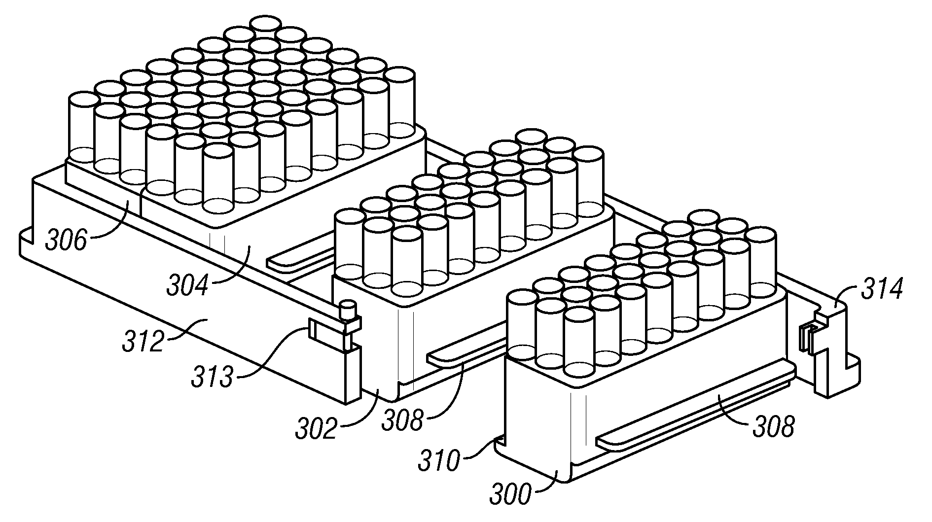
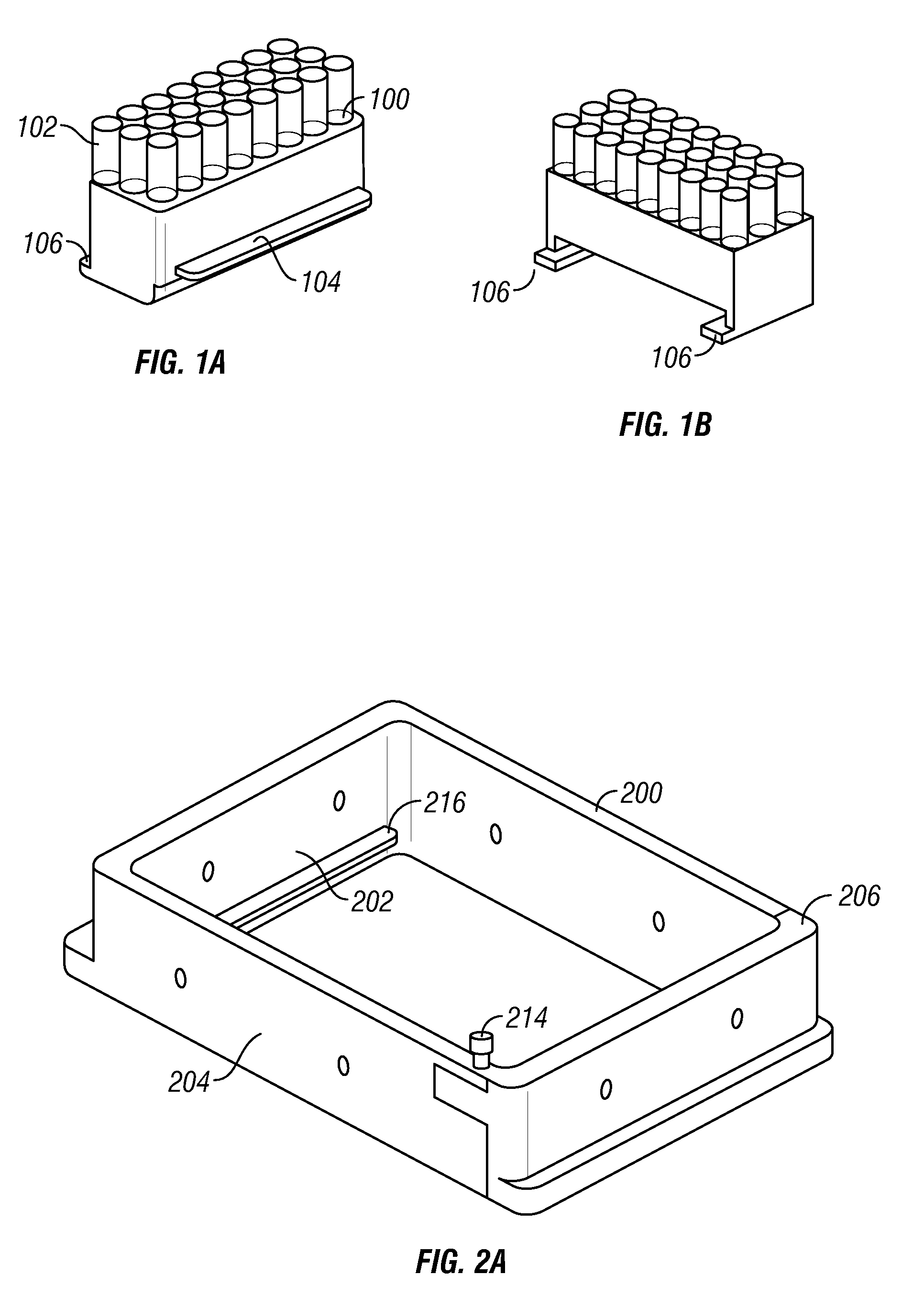
[0020]In one embodiment, a modular test tube rack comprises two or more sub-racks, each capable of holding multiple test tubes. One embodiment of a sub-rack is depicted in FIGS. 1A and 1B. The sub-rack has a plurality of holes 100 in which test tubes 102 can be inserted. In the embodiment shown in FIG. 1, the sub-rack holds 24 test tubes. The sub-rack also has a mechanism for removably coupling one sub-rack to another sub-rack. In one embodiment, as illustrated in FIG. 1, the mechanism for coupling sub-racks comprises a tongue 104, a lower flange 106, and a groove 108. When coupling two sub-racks together, the tongue 104 of one sub-rack overlaps with the lower flange 106 of the other sub-rack and fits within the groove. In this manner, multiple sub-racks can be strung together to form a larger test tube rack. It will be appreciated that a wide variety of mechanical couplings could be utilized. As another example, one or more protruding dowels might be provided on the front surface o...


PUM


Abstract

Disclosed herein is a modular test tube rack. The rack contains multiple sub-racks that can be coupled together to form the test tube rack. The sub-rack can be designed to fit into a variety of scientific instrumentation including a fixed rotor centrifuge. The assembled test tube rack can be of a format and size that allows use of standard array pipetters. Thus, a system is provided allowing use of standard array pipetters and high g centrifugation.

Description

BACKGROUND OF THE INVENTION[0001]1. Field of the Invention[0002]The present invention relates to scientific instrumentation. More particularly, the present invention relates to microtiter plates and test tube racks.[0003]2. Description of the Related Art[0004]The standard 96-well test tube racks and 96-well microtiter plates are a workhorse in the life science, biotechnology, and pharmaceutical industry. Under the specifications of the industry standard defined by the Society for Biomolecular Screening (SBS), the 96 wells are arranged in a rectangular matrix of 8 rows×12 columns, with a pitch size of 9 mm. The overall dimensions of the plate are defined by its outer skirt, which is 127.6 mm×85.3 mm. Higher-density plates are based on this basic design, with the outside, skirt dimensions being maintained constant while the pitch size is reduced by ½ for 384-well plates, by ¼ for 1536-well plates and by ⅙ for 3456-well plates.[0005]The usefulness of these items is significantly extend...

Claims


Application Information

Patent Timeline
Patent Type & Authority Patents(United States)
IPC IPC(8): B01L9/00B01L3/00B01L9/06
CPCB01L9/06B01L3/50855Y10T436/111666Y10S436/809
Inventor SINCLAIR, JAMES E.GROT, BRIAN
Owner VERTEX PHARMA INC
Why Eureka
Try Eureka