X-ray CT apparatus and image-taking method therefor

a technology of ct apparatus and x-ray, which is applied in the field of x-ray ct apparatus, can solve the problems of reducing diagnostic efficiency, affecting diagnosis, and causing significant deterioration of images

Inactive Publication Date: 2009-06-30
CANON KK
View PDF18 Cites 2 Cited by
  • Summary
  • Abstract
  • Description
  • Claims
  • Application Information

AI Technical Summary

Benefits of technology

[0012]The present invention has been implemented in consideration of the foregoing problems and provides a technology related to an X-ray CT apparatus that reduces an effect of a deviation of the revolution center point.

Problems solved by technology

If the projection data whose coordinate system has been shifted in such a way is considered as if not shifted and is reconstructed as it is, an artifact or significant deterioration in an image may be caused.
However, when the position deviation of the revolution center point is detected by utilizing a calibration phantom, it is necessary to newly create a calibration phantom, and, further, it takes a time to collect data, while taking images of the phantom, whereby the efficiency is lowered.
In addition, when a marker is used, it is necessary to newly create a marker; because the marker appears in a reconstructed tomographic image, diagnosis is hindered.

Method used


Image

  • X-ray CT apparatus and image-taking method therefor
  • X-ray CT apparatus and image-taking method therefor
  • X-ray CT apparatus and image-taking method therefor

Examples


embodiment 1

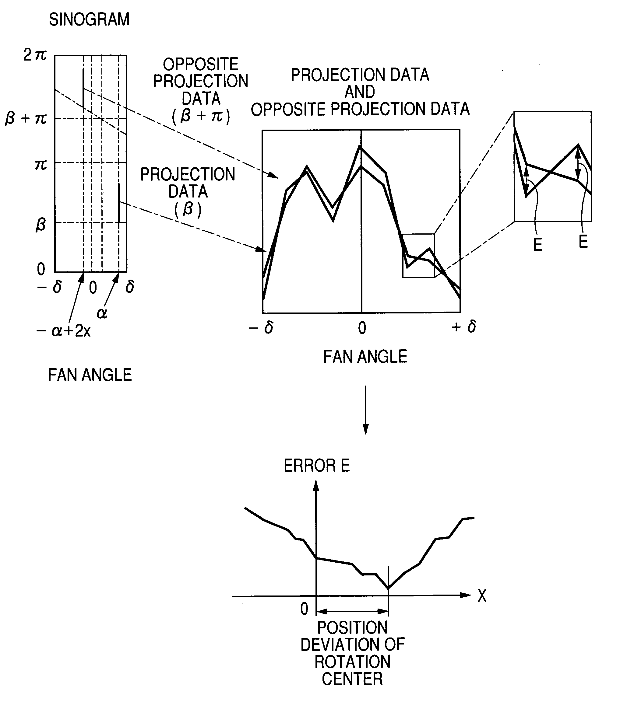
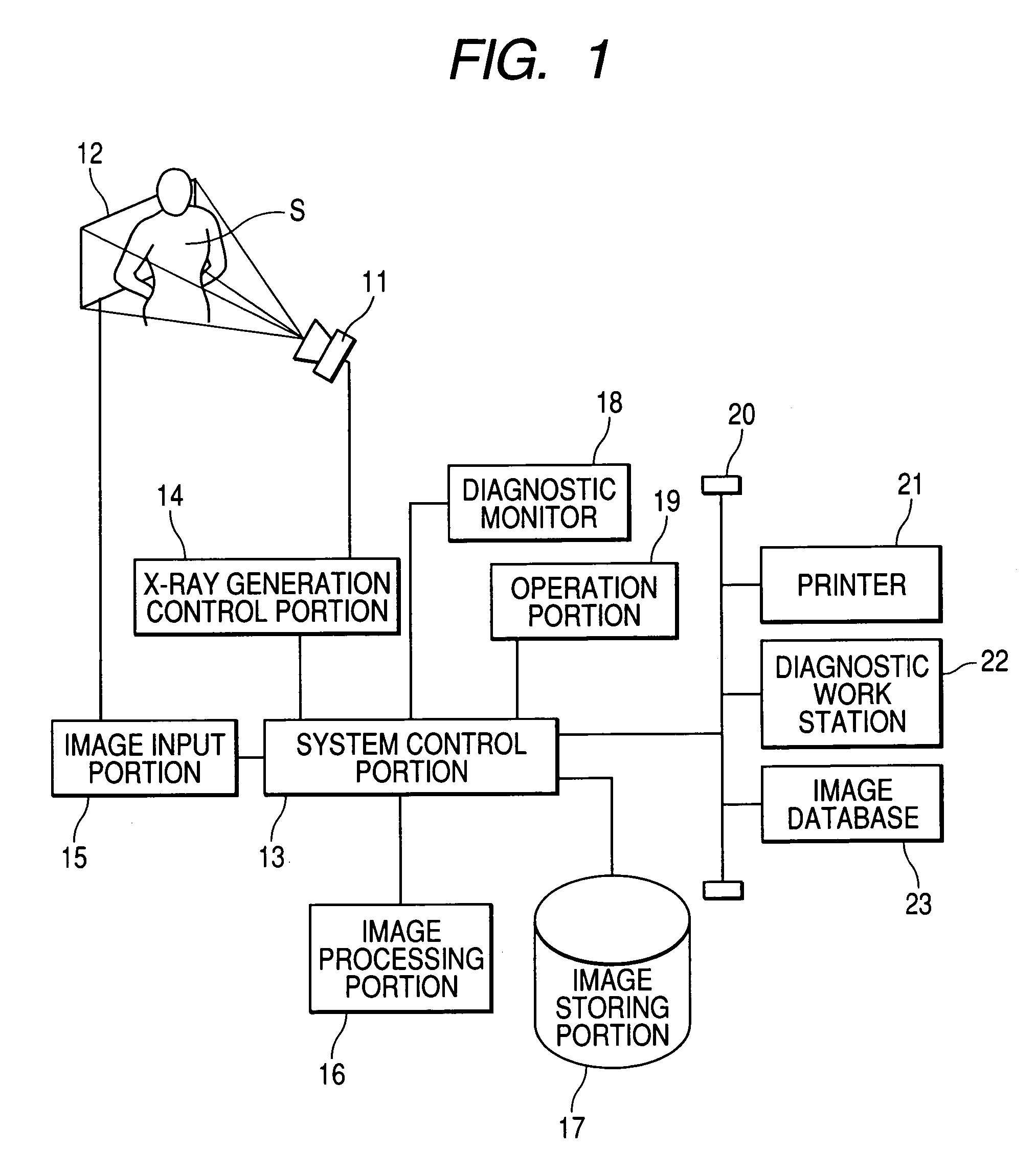
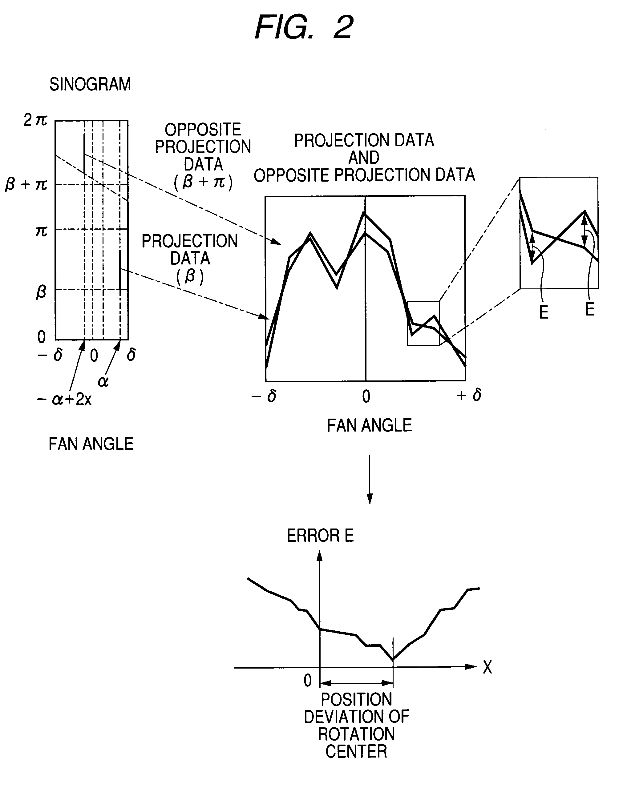
[0025]FIG. 1 is a block diagram of an X-ray CT system. An X-ray source 11 and an X-ray detector 12 are arranged, with a subject S, which is a patient, being interposed between them; the output of an system control portion 13 is connected via an X-ray generation control portion 14 to the X-ray source 11. In addition, the output of the X-ray detector 12 is connected via an image inputting portion 15 to the system control portion 13. Moreover, an image processing portion 16, an image storing portion 17, a diagnosis monitor 18, an operation portion 19, and a network 20 are connected to the system control portion 13; a printer 21, a diagnosis workstation 22, and an image database 23 are connected to the network 20.

[0026]An X-ray generated in the X-ray source 11 controlled by the X-ray generation control portion 14 penetrates the subject S and then is detected by the X-ray detector 12; the detected X-ray is inputted as a projection image to the system control portion 13, via the image inp...


PUM


Abstract

Time-series data over the range of a projection angle is created from a sinogram. Then, time-series data made up of opposite data corresponding to the time-series data over the range of a projection angle is created. Based on the amount of the error between the two types of time-series data, the amount of position deviation of a revolution axis is calculated.

Description

BACKGROUND OF THE INVENTION[0001]1. Field of the Invention[0002]The present invention relates to an X-ray CT apparatus for reconstructing tomographic images, by utilizing projection data.[0003]2. Related Background Art[0004]As illustrated in FIG. 4, in an X-ray CT (Computer Tomography) apparatus, an X-ray source 1 and an X-ray detector 2 are arranged so as to face each other, with a subject S being interposed between them; while the X-ray source 1 and the X-ray detector 2 or the subject S is are being revolved around a point within the subject S, each X-ray sequentially radiated by the X-ray source 1 is detected by the X-ray detector 2. By reconstructing and processing projection data created in this way, a tomographic image can be obtained. In this situation, the line that connects the X-ray source 1 with the center of the X-ray detector 2, i.e., the coordinate origin O for the projection data always passes through the revolution center point A.[0005]However, if, due to mechanical ...

Claims


Application Information

Patent Timeline
Patent Type & Authority Patents(United States)
IPC IPC(8): A61B6/00A61B6/03
CPCA61B6/032A61B6/583
Inventor URUSHIYA, HIROYUKI
Owner CANON KK
Why Eureka
Try Eureka