
Image highlight correction using illumination specific HSV color coordinate

a color coordinate and image technology, applied in image enhancement, instruments, image data processing, etc., can solve the problems of not being able to meet the high-speed requirements of machine vision applications, cannot be applied flexibly to objects in all environments, and cannot be effective in correct estimation of object colors, etc., to achieve the effect of accurate estimation of object colors and fast methods

Inactive Publication Date: 2009-06-30
PISHVA DAVAR
View PDF2 Cites 16 Cited by
  • Summary
  • Abstract
  • Description
  • Claims
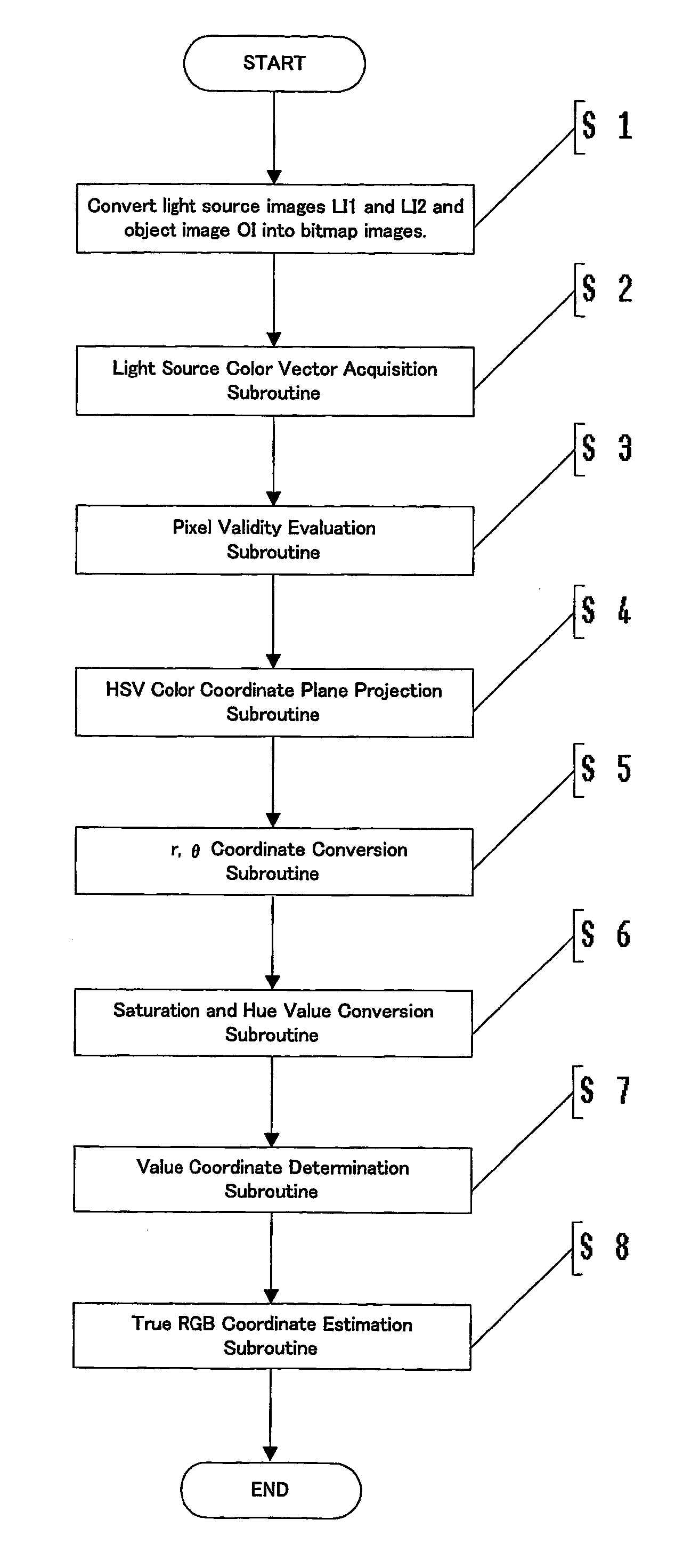
  • Application Information

AI Technical Summary

Benefits of technology

[0008]An object of this invention is therefore to provide a fast highlight correction method that can be implemented in a single illumination and single image setup, which does not require specialized apparatus or setup environment. Another object of this invention is to enable, for at least the unsaturated or valid pixels of the image of an object, the determination of the true color of each pixel independently of the other pixels to thereby enable the true colors of an object, having fine or intricate color variations, to be estimated readily. Yet another object of this invention is to introduce a new multiple illumination, multiple view, or combined multiple illumination and multiple view method as an alternative means for more accurate estimation of the object colors of the strongly highlighted parts, which completely saturate the imaging device's detecting elements that capture the highlighted segments.
[0010]In estimating the true object color, this method divides the image data into a group of valid pixels, for which the imaging device's detecting elements have not been saturated (e.g., on which the DRM can be used), and a group of non-valid pixels, for which the imaging device's detecting elements have been saturated. Accurate object colors of the valid pixel group are estimated by projecting the pixels along the light source vector onto the S-H plane of the illumination specific HSV color coordinate system and determining highlight free HSV color coordinates for the pixels. The approach enables true object color estimation of each pixel independent of other pixels, thus allowing the true colors of an object having fine or intricate variations of color to be estimated readily. The true RGB color coordinates of each non-valid pixel is estimated using an association with the colors of neighboring non-highlighted pixels as non-valid pixels do not obey DRM.
[0011]This method enables the true colors of an object to be estimated using a single illumination source and a single image, thus providing the advantage of being a fast method, and can be implemented in a system that does not require a specialized apparatus or setup environment. Furthermore, for at least the valid pixels of the image of an object, the true color of each pixel is determined independently of the other pixels, thus enabling the true colors of an object, having fine or intricate variations of color, to be estimated readily.
[0012]For an imaging environment where non-valid pixels constitute a considerable portion of the image, the new art introduces a new multiple illumination, multiple view, or combined multiple illumination and multiple view method for more accurate estimation of the object colors of the strongly highlighted (saturated) image segments. In the proposed multiple illumination, multiple view, or combined multiple illumination and multiple view approach, for each abovementioned non-valid pixel, a corresponding valid pixel is obtained from the other image(s). Though this approach utilizes more than one image or light source, it uses the RGB projection approach for image highlight correction, thus still maintaining the advantage of enabling the true colors of an object, having fine or intricate variations of color, to be estimated readily. Furthermore, a minimum of two images or illumination is sufficient for this purpose, as specular reflectance observed in a pixel of one image will not be observed in the corresponding pixel of another image captured under a different setup of illumination, view, or combination thereof.

Problems solved by technology

However, the approach is not effective for correct estimation of object colors when an analyzed region of the image consists of several different color clusters, as in the case of an image of an object with fine or intricate color variations.
Furthermore, both of the above methods require specialized apparatus (i.e. multiple light sources or a device enabling the capturing of images from different orientations) and setup environment and take long processing times. These methods therefore cannot be applied flexibly to objects under all environments and do not adequately answer the high-speed requirements of machine vision applications.

Method used


Image

  • Image highlight correction using illumination specific HSV color coordinate
  • Image highlight correction using illumination specific HSV color coordinate
  • Image highlight correction using illumination specific HSV color coordinate

Examples


Embodiment Construction

[0028]First, the relationship of RGB color space and HSV color space, which is relevant to understanding this invention, shall be described briefly.

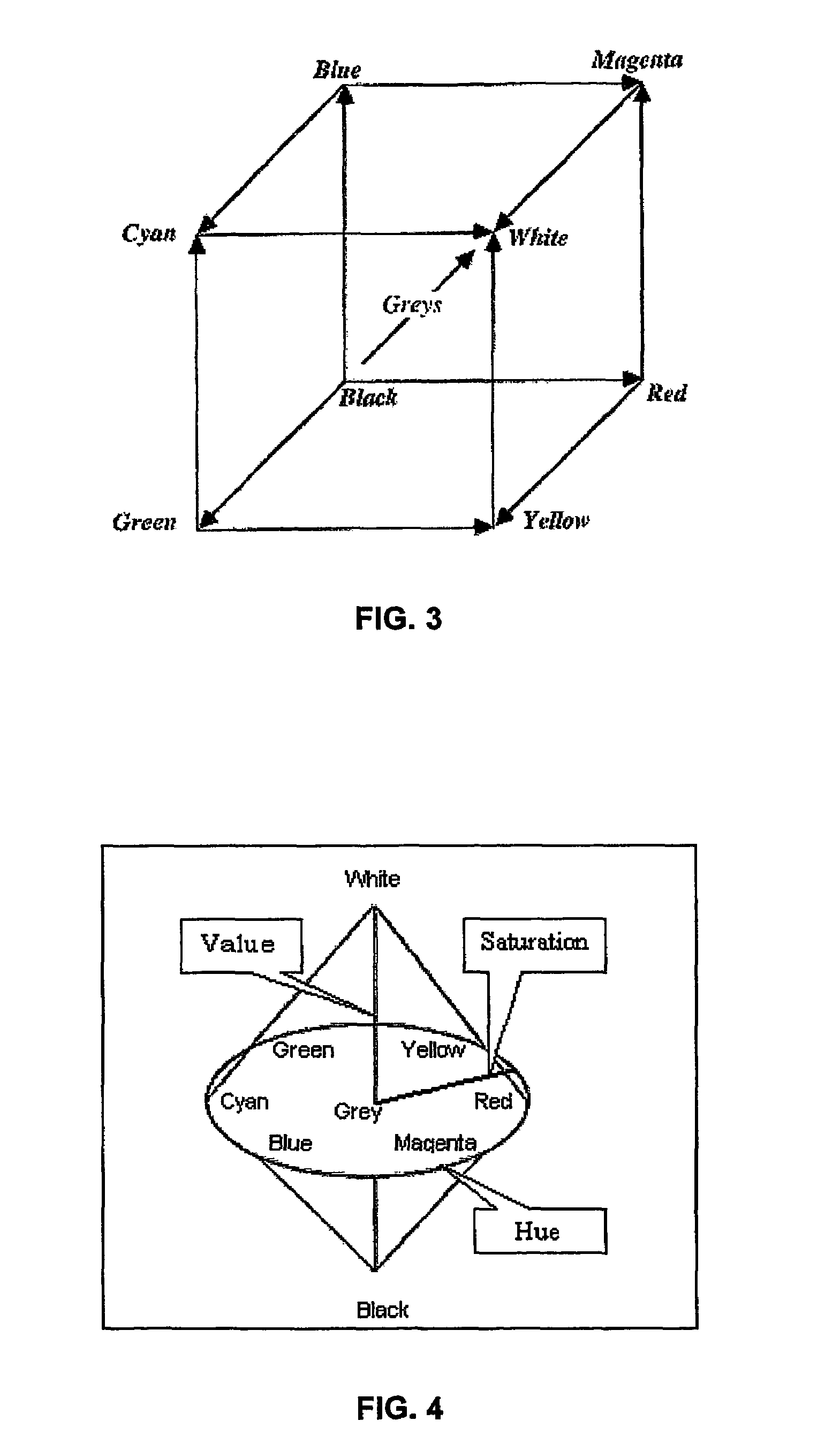
[0029]RGB color space is a hardware-oriented scheme that is based on the way camera sensors and display phosphors work. In RGB color space, the three primary colors of red, green and blue are assigned to the three independent axes of a cube as shown in FIG. 3. In this space, the grey scale lies along the cube diagonal with additive progression from black to white. The complementary colors of cyan, magenta, and yellow (CMY), which are used for printing, are located on the opposite corners such that combining green and blue produce cyan, blue and red produce magenta, and red and green produce yellow.

[0030]Although RGB color space is very useful for image representation, there are other encoding schemes that are more useful in image analysis. One such color space is hue, saturation and value (HSV) color space, which is illustrated in FIG. 4...


PUM


Abstract

An image highlight correction method comprising the steps of mapping the image data from RGB color coordinates to an illumination specific HSV color coordinate system the value axis of which is in the direction of the light source, estimating highlight free HSV coordinates for each pixel, and restoring a highlight free image in RGB representation. Image highlight correction programs and image acquisition systems that make use of this image highlight correction method are also disclosed.

Description

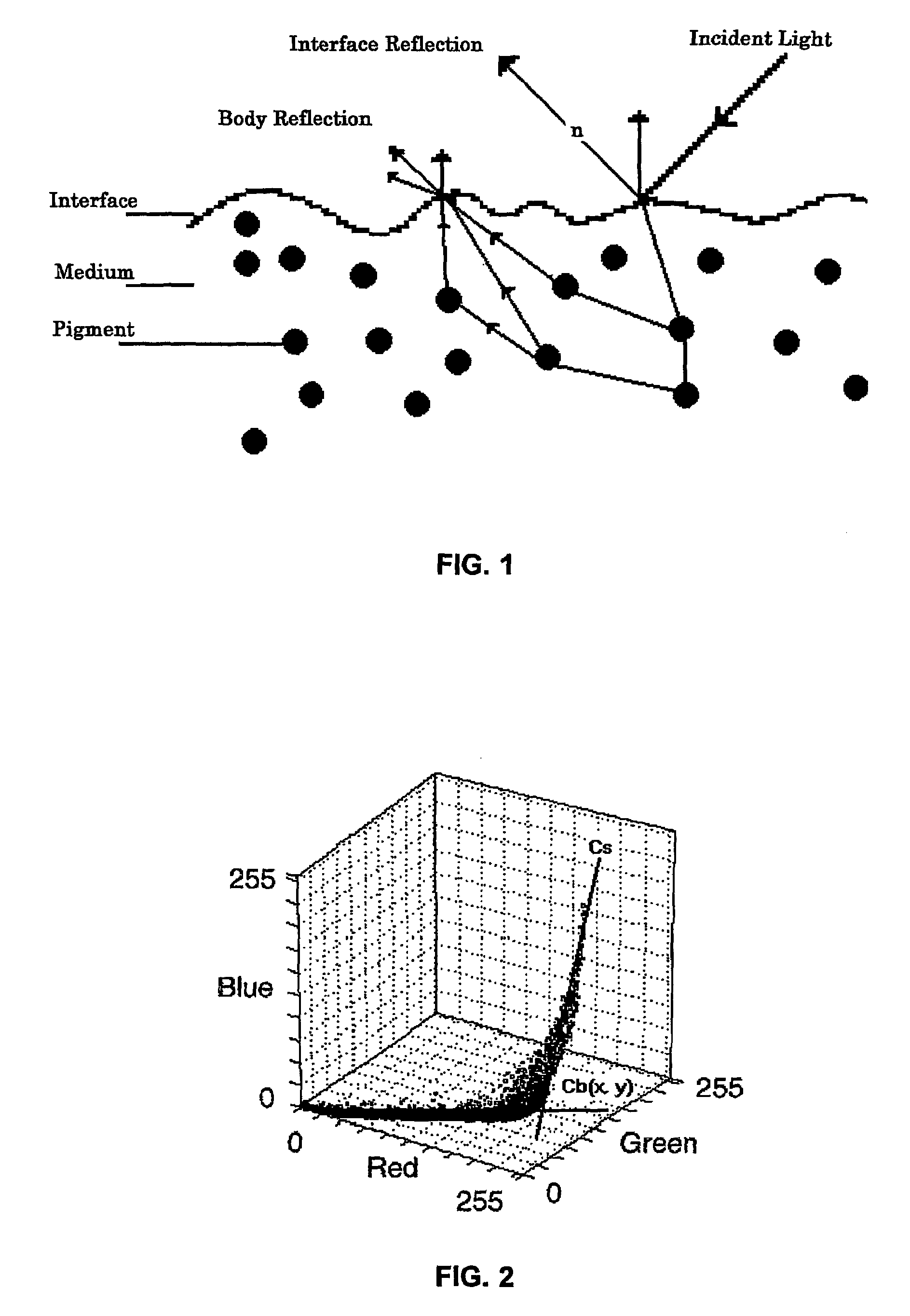
TECHNICAL FIELD[0001]This invention concerns a method for estimating the underlying colors of image highlights in machine vision applications. Most machine vision applications involve analysis of images resulting from the reflectance of light. Object surface color is one of the most important pieces of information for computer vision. Colors recorded as images, however, do not specify the true colors of an object's surface. They also contain specular or interface reflectance, which appears as highlight or gloss on the object. In some cases, the highlight may be so strong that an imaging device's detecting elements, which capture the highlighted parts, become saturated.BACKGROUND ART[0002]When we look at reflected light L of a dielectric material, such as plastic, we usually see two distinct reflection components: a specular or interface reflection component Ls and a diffuse or body reflection component Lb. The specular or interface reflection occurs at the surface and in only one di...

Claims


Application Information

Patent Timeline
Patent Type & Authority Patents(United States)
IPC IPC(8): G06K9/00G01J3/46G06T1/00G06T5/00G06T15/50H04N1/407H04N1/46H04N1/60
CPCG06T15/506H04N1/6086
Inventor PISHVA, DAVAR
Owner PISHVA DAVAR
Learn More