High altitude platform deployment system

a platform and high-altitude technology, applied in the field of high-altitude platform deployment systems, can solve problems such as difficulty in adapting to changing wind-speed and weather conditions, and achieve the effect of increasing energy generation efficiency

Active Publication Date: 2009-06-30
AEROVIRONMENT INC
View PDF19 Cites 13 Cited by
  • Summary
  • Abstract
  • Description
  • Claims
  • Application Information

AI Technical Summary

Benefits of technology

[0011]Further embodiments of the invention feature the use of full high-power-generation flight patterns. Generally, these embodiments provide additional energy generating efficiency.

Problems solved by technology

A limited number of aircraft have been developed for deployment as high-altitude platforms, such as for communication relay systems, which require both high-altitude flying and tight stationkeeping.
However, the limited number of aircraft that can sustain continuous flight for significant lengths of time typically have limited airspeed ranges, and thus have difficulty in their ability to adapt to changing wind-speeds and weather conditions during flight.

Method used


Image

  • High altitude platform deployment system
  • High altitude platform deployment system
  • High altitude platform deployment system

Examples


first embodiment

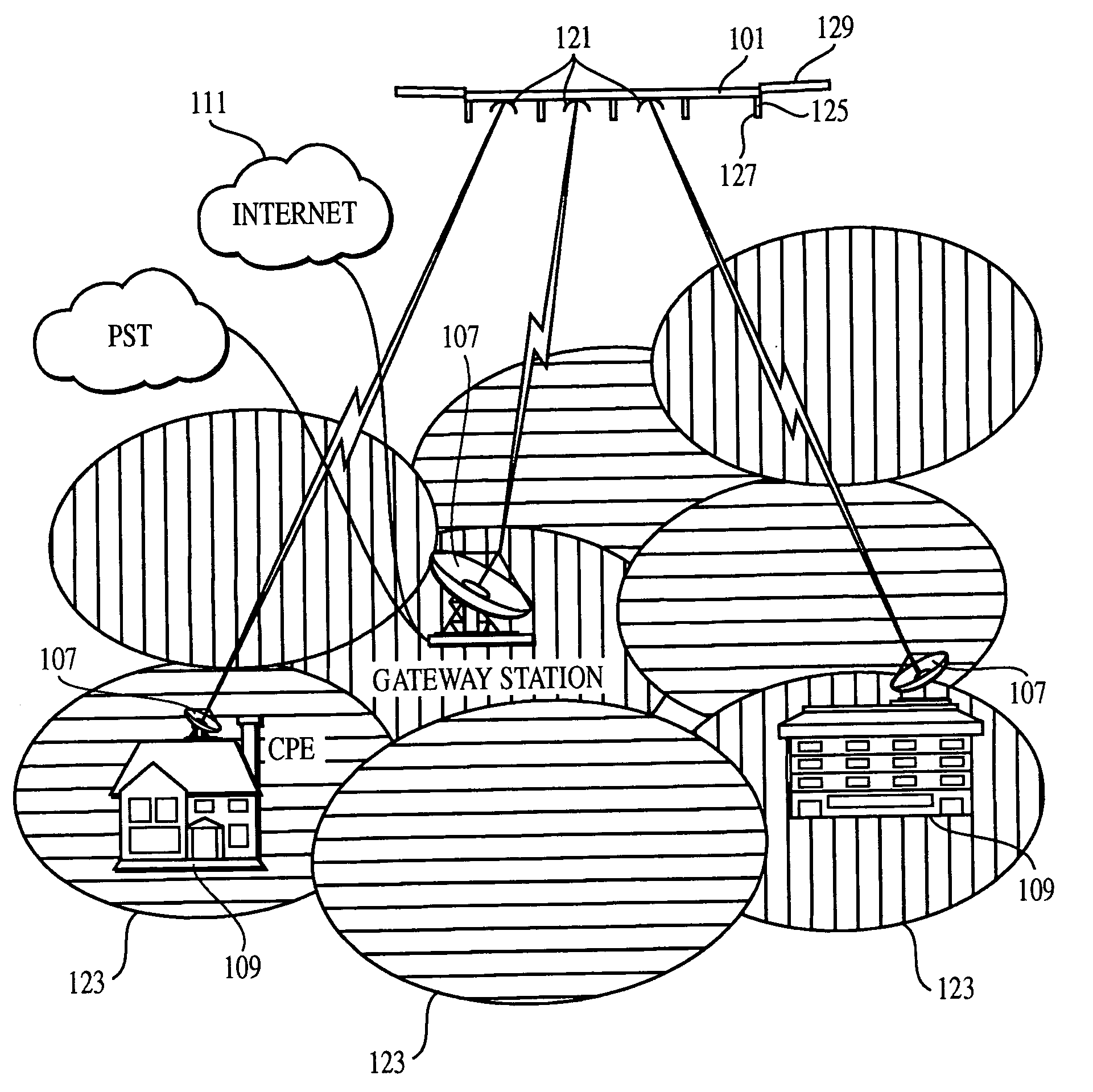
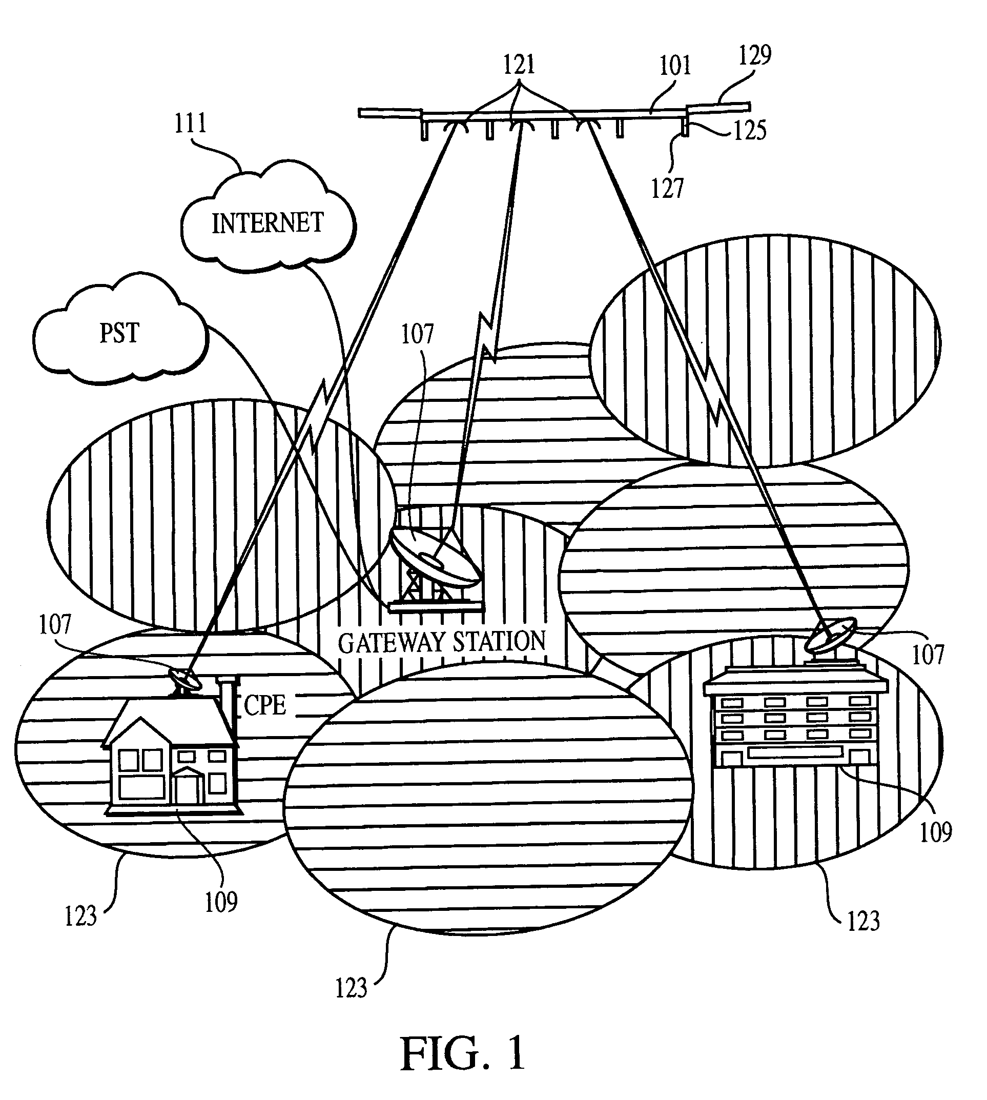
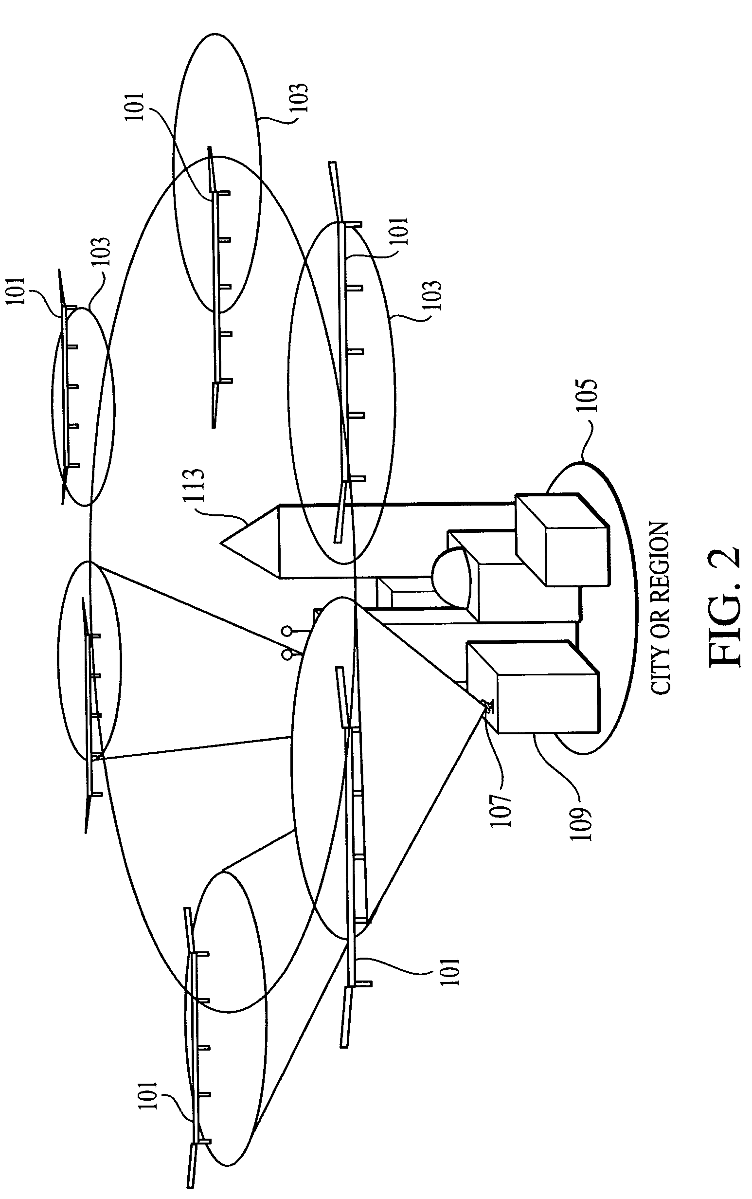
[0030]While the communication system antennas 121 of each aircraft 101 support communication signals with a substantial portion of the target market area 105, the control system 125 preferably controls flight controls of the aircraft so as to keep the aircraft in the flight station 103, and such that it could be maintained in the flight station indefinitely. In this first embodiment of the invention, the aircraft power system and the control system are preferably configured to maintain the aircraft, and operate the communication relay system, for a period of at least a plurality of days, and more preferably for more than a week, or even more than a month at a time. Preferably the aircraft replenishes its power supplies by using solar cells.

[0031]The ability of the aircraft 101 to stay within a tight flight station 103 depends upon the airspeed range of the aircraft, and upon the true wind speeds at the flight station. To maintain the aircraft in the flight station in varying conditi...

second embodiment

[0054]With reference to FIG. 5, in the northern hemisphere each aircraft of the second embodiment's first and second pluralities of aircraft flies a partial fly-from-sun pattern. In particular, an afternoon aircraft (i.e., an aircraft maintaining the flight station in the afternoon) would be flying west at a sunrise location 301 when the sun rises. The afternoon aircraft slowly turns toward the north throughout the morning so as to fly away from the sun until half of the daytime (i.e., the daylight portion of the day) has past. At this point it is flying substantially northward, and it reaches the flight station 303. Through this first half of the daytime, the afternoon aircraft has taken significant advantage of the morning sunlight.

[0055]The afternoon aircraft then relieves a morning aircraft that was maintaining the flight station 303. The morning aircraft then assumes the northbound flight pattern, slowly turning east as the sun moves to the western horizon. At the point of suns...

third embodiment

[0066]Unlike the first two embodiments, the third embodiment does not typically have tight flight stations. Instead, it is configured with broad flight stations so that at least one aircraft is in effective communications range at all times. Actively tracking, limited beamwidth, ground-based antennas will generally be used for this embodiment, as the antennas will have to both follow moving aircraft, and periodically re-target on new aircraft. Alternatively, significantly wider beamwidth, ground-based antennas or omnidirectional antennas could be used.

[0067]This embodiment allows for lower cost aircraft to be used. In particular, cost savings can be achieved by using less-efficient solar cells on an aircraft configured to provide service over a given area. Additionally, this embodiment has the potential to allow a given aircraft to be used at higher latitudes than could otherwise be handled by a tight stationkeeping embodiment. The embodiment can be used in higher latitudes because ...


PUM


Abstract

A communication system for supporting communications with a target market area. The system includes one or more solar-powered aircraft maintained in, or successively passing through, flight stations or flight patterns around the market area. Each of the aircraft targets limited beamwidth communication antennas on a substantial portion of the target market area. The control system is configured to fly selective flight patterns depending on the aircraft characteristics and the flight conditions. The flight patterns may emphasize high-power-generation patterns such as flying away from the sun for aircraft with wing-mounted solar cells.

Description

[0001]This application claims priority from U.S. provisional patent application 60 / 373,336, filed Apr. 17, 2002, which is incorporated herein by reference for all purposes.BACKGROUND[0002]This invention relates generally to methods and systems of deploying aircraft for use as atmospheric platforms, and more particularly, to communication systems employing aircraft as high-altitude platforms.[0003]Among the many types of aircraft (e.g., balloons, dirigibles, traditional fixed wing airplanes, flying wing airplanes and helicopters), some are capable of high-altitude flight, and some are capable of hovering or maintaining a relatively small flight station (i.e., a small, laterally and vertically limited airspace) with respect to the ground (“stationkeeping”). A limited number of aircraft have been developed for deployment as high-altitude platforms, such as for communication relay systems, which require both high-altitude flying and tight stationkeeping. Such aircraft are preferably sol...

Claims


Application Information

Patent Timeline
Patent Type & Authority Patents(United States)
IPC IPC(8): H04W4/00H04B7/185
CPCH04B7/18504
Inventor HIBBS, BART D.COX, EARL C.
Owner AEROVIRONMENT INC
Why Eureka
Try Eureka