Inkjet printhead integrated circuit with ink spread prevention

a technology of inkjet printhead and integrated circuit, which is applied in the direction of printing, etc., can solve the problems of difficult to fabricate a suitable covering for the components and easily damaged components, and achieve the effect of facilitating relative displacement of the cover

Inactive Publication Date: 2009-07-07
SILVERBROOK RES PTY LTD +1
View PDF83 Cites 42 Cited by
  • Summary
  • Abstract
  • Description
  • Claims
  • Application Information

AI Technical Summary

Benefits of technology

[0032]The roof wall may define a cover that spans the walls to cover the elongate actuator. The motion-transmitting structure may be shaped so that the cover and the motion-transmitting structure define generally co-planar surface

Problems solved by technology

As set out in the above referenced applications/patents, the Applicant has spent a substantial amount of time and effort in developing printheads that incorporate micro electro-mechanical system (MEMS)—based components to achieve the ejection of ink necessary for printing.
However, on a macroscopic scale, the vario

Method used


Image

  • Inkjet printhead integrated circuit with ink spread prevention
  • Inkjet printhead integrated circuit with ink spread prevention
  • Inkjet printhead integrated circuit with ink spread prevention

Examples


Embodiment Construction

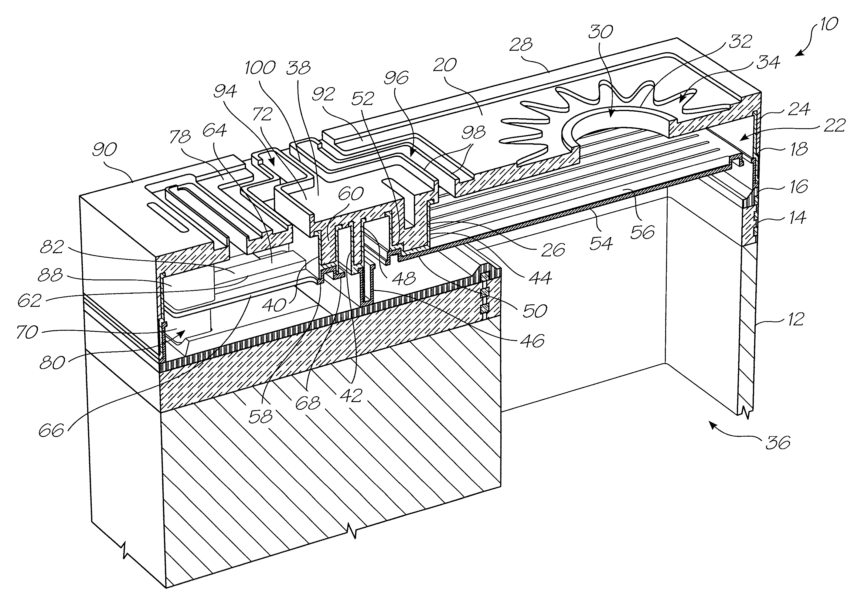
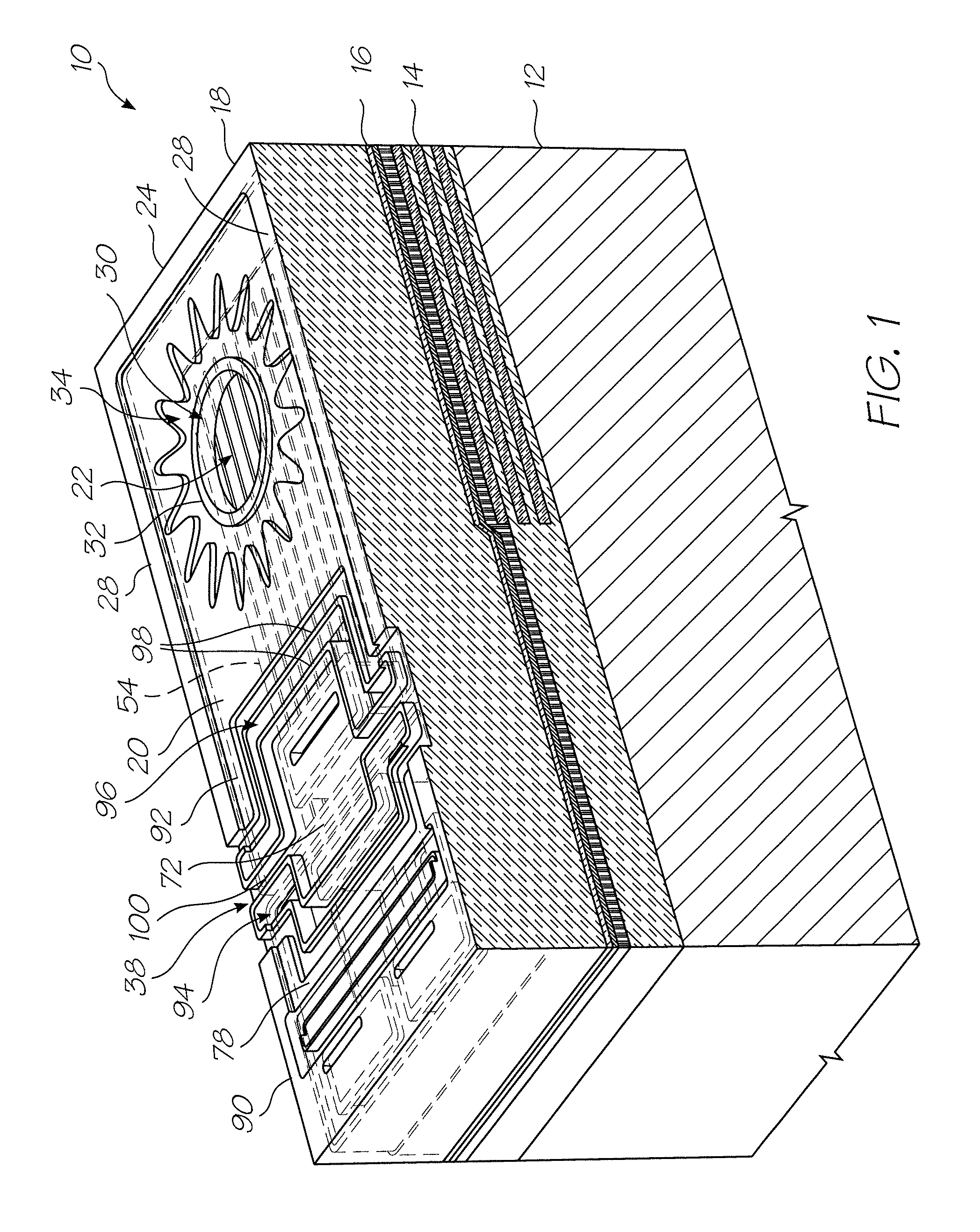
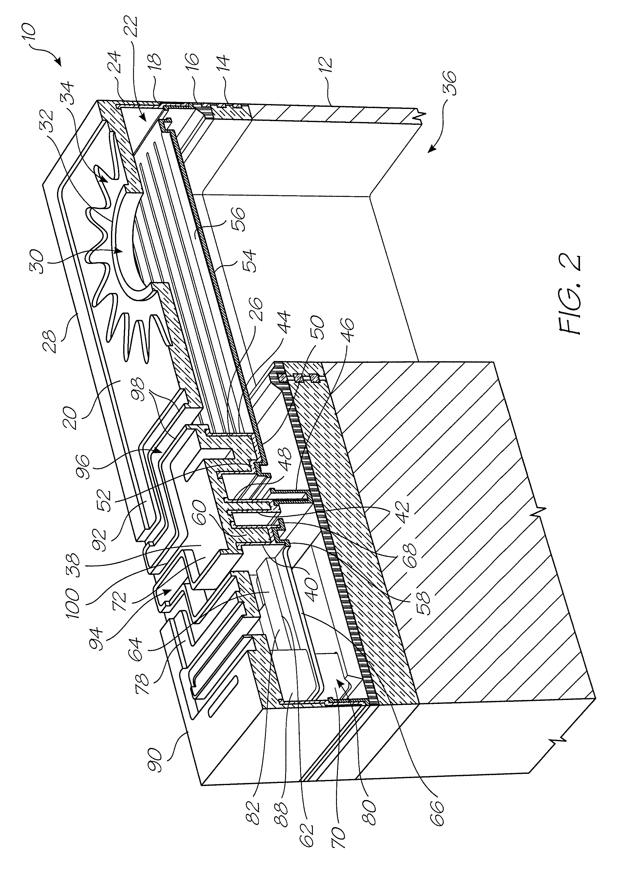
[0049]In the drawings, reference numeral 10 generally indicates a nozzle arrangement for a first embodiment of an ink jet printhead chip, in accordance with the invention.

[0050]The nozzle arrangement 10 is one of a plurality of such nozzle arrangements formed on a silicon wafer substrate 12 to define the printhead chip of the invention. As set out in the background of this specification, a single printhead can contain up to 84 000 such nozzle arrangements. For the purposes of clarity and ease of description, only one nozzle arrangement is described. It is to be appreciated that a person of ordinary skill in the field can readily obtain the printhead chip by simply replicating the nozzle arrangement 10 on the wafer substrate 12.

[0051]The printhead chip is the product of an integrated circuit fabrication technique. In particular, each nozzle arrangement 10 is the product of a MEMS—based fabrication technique. As is known, such a fabrication technique involves the deposition of functio...


PUM


Abstract

An inkjet printhead integrated circuit includes a silicon wafer substrate that defines a plurality of ink inlet channels. An electrical drive circuitry layer is positioned on the silicon wafer substrate for connection to a suitable microprocessor. A plurality of replicated nozzle arrangements is positioned on the substrate to receive an enabling signal from the microprocessor. Each nozzle arrangement has nozzle chamber walls and a roof positioned on the nozzle chamber walls to define a nozzle chamber in fluid communication with a respective ink inlet channel with the roof defining an ink ejection port in fluid communication with the nozzle chamber and a recess about the ink ejection port to inhibit ink spread.

Description

CROSS-REFERENCE TO RELATED APPLICATIONS[0001]The present application is a Continuation of U.S. application Ser. No. 11 / 442,179 filed May 30, 2006, now issued U.S. Pat. No. 7,246,884, which is a Continuation of U.S. application Ser. No. 11 / 172,810 filed Jul. 5, 2005, now issued U.S. Pat. No. 7,055,935, which is a Continuation of U.S. application Ser. No. 10 / 962,394 filed on Oct. 13, 2004, now issued U.S. Pat. No. 6,948,799, which is a Continuation of U.S. application Ser. No. 10 / 713,072 filed Nov. 17, 2003, now U.S. Pat. No. 6,824,251, which is a Continuation of U.S. application Ser. No. 10 / 302,556 filed Nov. 23, 2002, now issued U.S. Pat. No. 6,666,543, which is a Continuation of U.S. application Ser. No. 10 / 120,346 filed Apr. 12, 2002, now issued U.S. Pat. No. 6,582,059, which is a Continuation-in-Part of U.S. application Ser. No. 09 / 112,767 filed Jul. 10, 1998, now issued U.S. Pat. No. 6,416,167 all of which are herein incorporated by reference.FIELD OF THE INVENTION[0002]This inv...

Claims


Application Information

Patent Timeline
IPC IPC(8): B41J2/04
CPCB41J2/14427
Inventor SILVERBROOK, KIA
Owner SILVERBROOK RES PTY LTD
Why Eureka
Try Eureka