Transmittance adjuster unit, a planar illumination device, a liquid crystal display device using the same, and a method of arranging transmittance adjusters

a technology of transmittance adjuster and transmittance adjuster, which is applied in the direction of lighting and heating apparatus, instruments, optical elements, etc., can solve the problems of irregular luminance of illuminating, and achieve efficient reduction of luminance unevenness, without lowering luminance, and the effect of reducing luminance unevenness

Active Publication Date: 2009-07-07
FUJIFILM CORP
View PDF12 Cites 12 Cited by
  • Summary
  • Abstract
  • Description
  • Claims
  • Application Information

AI Technical Summary

Benefits of technology

[0046]According to the first and fourth aspects of the present invention, the pattern density of the transmittance adjusters that compose the transmittance adjuster unit satisfies the relationship set forth above and this enables light to be emitted from the light emission plane with the luminance unevenness being reduced efficiently but without lowering its luminance. In addition, since the luminance unevenness can be reduced efficiently, there is offered the advantage of permitting the use of an even thinner and more lightweight diffusion film.
[0047]According to the second aspect of the present invention, the planar illumination device has the transmittance adjuster unit provided on the light emission plane of the light guide plate, the side of the diffusion film closer to the light guide plate, or on the side of the diffusion film away from the light guide plate, or if a prism sheet is provided, the transmittance adjuster unit may be provided on the side of the prism sheet closer to the light guide plate or on the side of the prism sheet away from the light guide plate, and the pattern density of the transmittance adjuster unit satisfies the relationship set forth above; as a result, the luminance unevenness can be reduced efficiently and the diffusion film can be made thinner. In addition, with the luminance unevenness being reduced efficiently, the efficiency of light emission can be sufficiently increased that light of high luminance can be emitted even from a light source of low luminance.
[0048]As a result, there can be provided a planar illumination device that is thin, lightweight, can be manufactured at a lower cost, that can emit illuminating light of greater uniformity, smaller unevenness and higher luminance, and which can be applied to liquid crystal display devices such as a wall-hung TV.
[0049]According to a third aspect of the present invention, by using the planar illumination device according to the second aspect described above, there can be provided a liquid crystal display device that is thin, lightweight, can be manufactured at a lower cost, that can realize display of greater uniformity, smaller unevenness and higher luminance, and which can be designed as a wall-mounted type such as a wall-hung TV.

Problems solved by technology

However, the light guide plates described above all suffer the problem of causing luminance irregularities to the illuminating light emitting from the emission plane.

Method used


Image

  • Transmittance adjuster unit, a planar illumination device, a liquid crystal display device using the same, and a method of arranging transmittance adjusters
  • Transmittance adjuster unit, a planar illumination device, a liquid crystal display device using the same, and a method of arranging transmittance adjusters
  • Transmittance adjuster unit, a planar illumination device, a liquid crystal display device using the same, and a method of arranging transmittance adjusters

Examples


Embodiment Construction

[0081]Hereinafter, the transmittance adjuster unit, the planar illumination device, the liquid crystal display device using the same, and the method of arranging transmittance adjusters according to the present invention will be described in detail based on the preferred embodiments shown in the accompanying drawings.

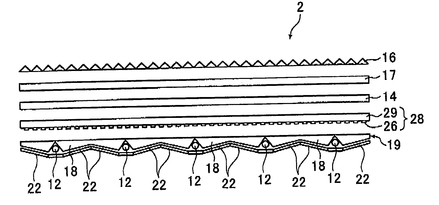
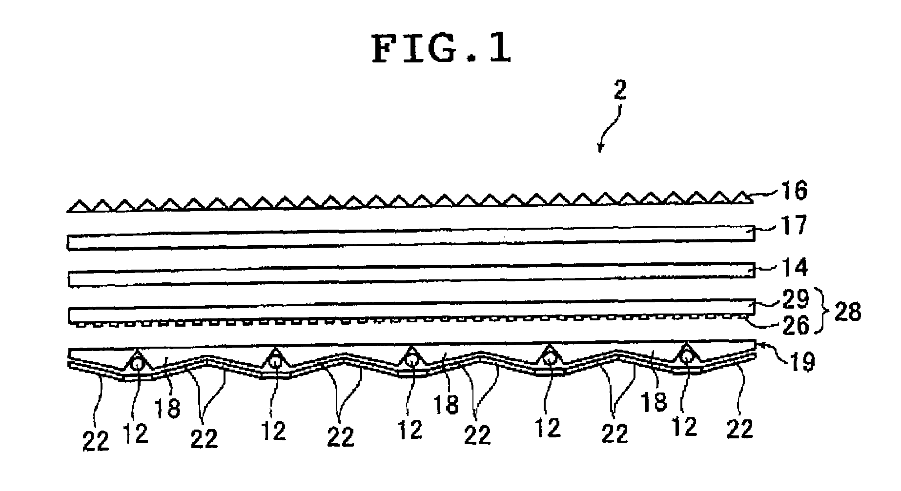
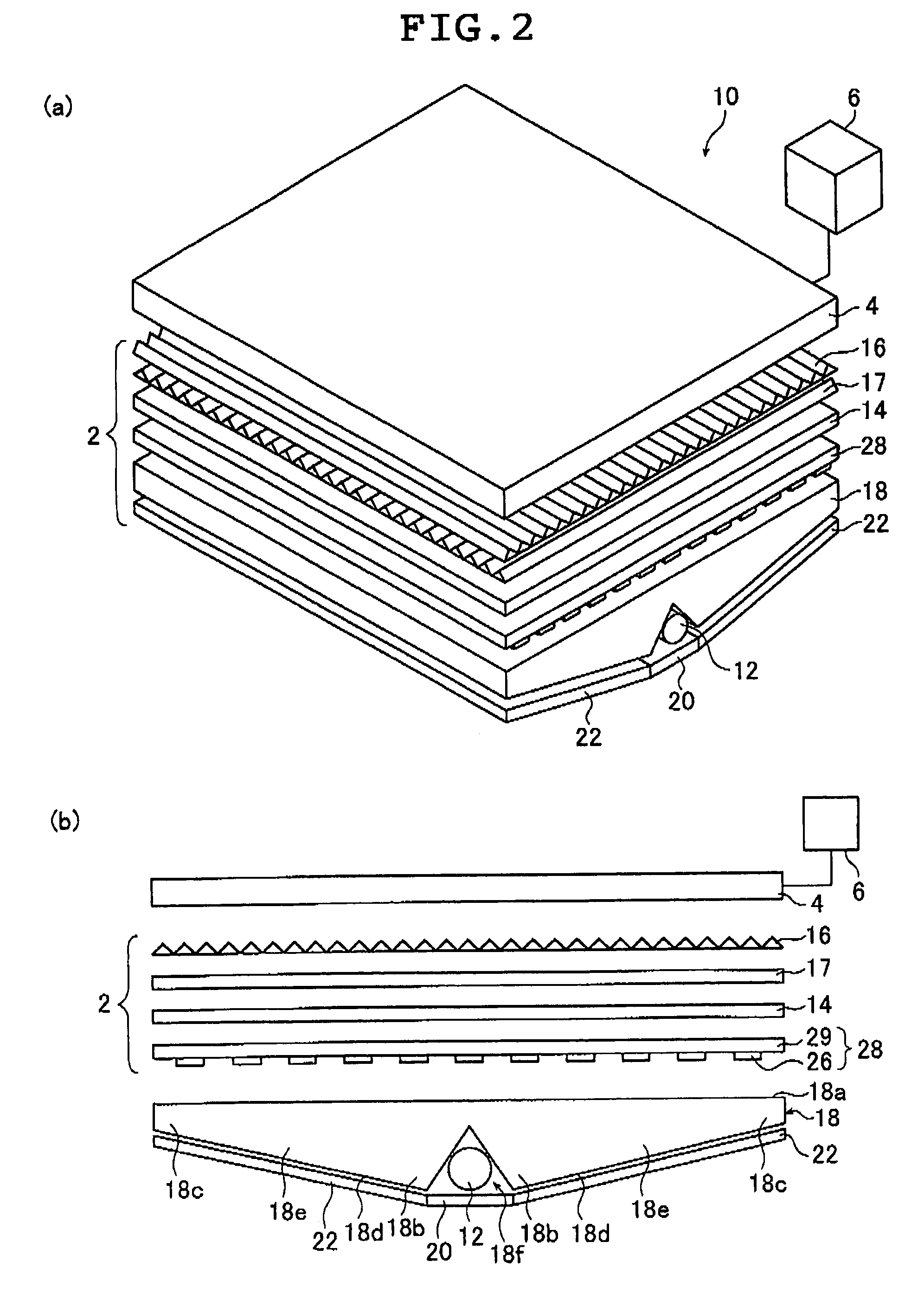
[0082]FIG. 1 is a schematic sectional view of a planar illumination device (hereinafter also referred to as a backlight unit) 2 according to the second aspect of the present invention that has a transmittance adjuster unit 28 according to the first aspect of the present invention. The planar illumination device 2 is used as a backlight unit for the liquid crystal display device according to the third aspect of the present invention. FIGS. 2(a) and (b) are a schematic partial perspective view and a schematic partial section that show part of a single light guide plate unit 18 in the backlight unit 2 shown in FIG. 1, as well as the liquid crystal display device 10 using t...


PUM


Abstract

A transmittance adjuster unit includes multiple transmittance adjusters arranged in a predetermined pattern, if the pattern density is ρ(x, y), the maximum luminance Fmax of the light emitted from the light emission plane of a planar illumination device when the unit is not provided is 1, the minimum luminance is Fmin, and the relative luminance with respect to the maximum luminance Fmax of the light emitted from a predetermined position (x, y) of the emission plane is F(x, y), the relationship between the luminance F(x, y) and the pattern density ρ(x, y) satisfies the following expression: ρ(x, y)=c{F(x, y)−Fmin} / (Fmax−Fmin), wherein 0.5≦c≦1. This unit is thin and lightweight, and can reduce unevenness of the luminance without reducing the average luminance of the incident light. The planar illumination device includes the transmittance adjuster unit and a liquid crystal display device includes the planar illumination device.

Description

TECHNICAL FIELD[0001]This invention relates to a transmittance adjuster unit that enables light emitting from the light emission plane of a light guide plate to become more uniform, as well as a planar illumination device that emits uniform light from the light emission plane, a liquid crystal display device using the same, and a method of arranging transmittance adjusters.BACKGROUND ART[0002]A liquid crystal display device is provided with a backlight unit that applies light to the back side of a liquid crystal panel (LCD) so as to illuminate it. The backlight unit is composed of such components as an illuminating light source, a light guide plate that diffuses light emitted from the light source so that it is applied to the liquid crystal panel, a prism sheet or diffusion sheet for rendering the light emitted from the light guide plate to become uniform.[0003]A known example of such backlight unit is disclosed in Patent Document 1.[0004]FIG. 25 is a schematic sectional view of an ...

Claims


Application Information

Patent Timeline
Patent Type & Authority Patents(United States)
IPC IPC(8): G01D11/28
CPCG02B6/0021G02B6/0046G02F1/133605G02B6/0038G02B6/0053G02F2001/133607G02F1/133604G02F1/133611G02B6/0055G02F1/133607
Inventor MATSUSHITA, MOTOHIKO
Owner FUJIFILM CORP
Why Eureka
Try Eureka