Bi-layer tip cap

a technology of tip cap and layer, which is applied in the direction of reaction engines, machines/engines, engine fuctions, etc., can solve the problems of insufficient creep strength of most alloys, and prone to bulging of the tip cap, etc., to achieve high strength, high strength, and high strength

Inactive Publication Date: 2009-07-07
GENERAL ELECTRIC CO
View PDF13 Cites 15 Cited by
  • Summary
  • Abstract
  • Description
  • Claims
  • Application Information

AI Technical Summary

Problems solved by technology

The tip cap also is prone to bulging due to creep.
Most alloys with sufficient creep strength do not have sufficient resistance to oxidation.
Most alloys with adequate oxidation resistance do not have sufficient creep strength.
Those alloys that do have adequate properties for both creep and oxidation generally are not available except as custom cast billets.
Such custom billets then have to be worked at great expense to form a finished product.

Method used


Image

  • Bi-layer tip cap
  • Bi-layer tip cap
  • Bi-layer tip cap

Examples


Embodiment Construction

[0018]Referring now to the drawings, in which like numerals refer to like parts throughout the several views, FIG. 1 depicts an example of a turbine bucket 10. The turbine bucket 10 may include a conventional dovetail 12. The dovetail 12 attaches to a conventional rotor disc (not shown). A blade shank 14 extends upwardly from the dovetail 12 and terminates in a platform 16 that projects outwardly from and surrounds the shank 14.

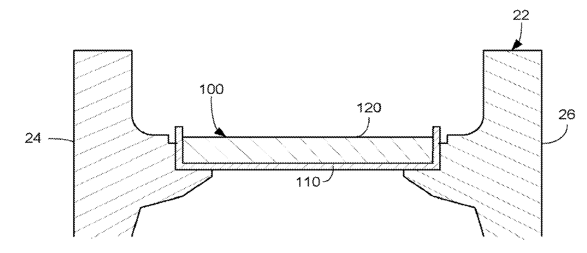
[0019]A hollow airfoil 18 extends outwardly from the platform 16. The airfoil 18 has a root 20 at the junction with the platform 16 and a tip 22 at its outer end. The airfoil 18 has a concave pressure sidewall 24 and a convex suction sidewall 26 joined together at a leading edge 28 and a trailing edge 30. The airfoil 18 may include a number of trailing edge cooling holes 32 and a number of leading edge cooling holes 33. A tip cap 34 may close off the tip 22 of the airfoil 18. A squealer tip 36 may extend outwardly from the tip cap 34.

[0020]The airfoil 18 may ...


PUM


Abstract

A tip cap for use in a turbine bucket. The tip cap may include a shield of an oxidant resistant material and a cap positioned within the shield of a high strength material.

Description

TECHNICAL FIELD[0001]The present invention relates generally to a turbine engine and more particularly relates to a bi-layer tip cap for a turbine bucket.BACKGROUND OF THE INVENTION[0002]In a gas turbine engine, air is pressurized in a compressor and then mixed with fuel and ignited in a combustor for generating hot combustion gases. The gases flow through turbine stages that extract energy therefrom for powering the compressor and producing useful work. A turbine stage includes a row of turbine buckets extending outwardly from a supporting rotor disc. Each turbine bucket includes an airfoil over which the combustion gases flow. The airfoils are generally hollow and may be provided with air bled from the compressor for use as a coolant during operation.[0003]Each turbine bucket includes a blade body and a tip cap. Due to the environment in which the tip cap operates, the tip cap should be oxidant resistant. The tip cap also is prone to bulging due to creep. Most alloys with sufficie...

Claims


Application Information

Patent Timeline
Patent Type & Authority Patents(United States)
IPC IPC(8): F01D5/28
CPCF01D5/20F05D2260/95F05D2230/90F05D2230/30
Inventor SHERLOCK, GRAHAM D.NOWAK, DANIEL A.BALSONE, STEPHEN J.MOHR, PATRICK J.
Owner GENERAL ELECTRIC CO
Why Eureka
Try Eureka