Discharge lamp lighting device, and lighting equipment and lighting system using the device
a technology of lighting device and discharge lamp, which is applied in the direction of dc-ac conversion without reversal, process and machine control, instruments, etc., can solve the problems of large measurement error, difficulty in adequately measuring the life end of inability to use the technique for a determination on the life end of the smoothing capacitor in the inverter device, etc., to achieve the effect of simplifying the configuration
- Summary
- Abstract
- Description
- Claims
- Application Information
AI Technical Summary
Benefits of technology
Problems solved by technology
Method used
Image
Examples
first embodiment
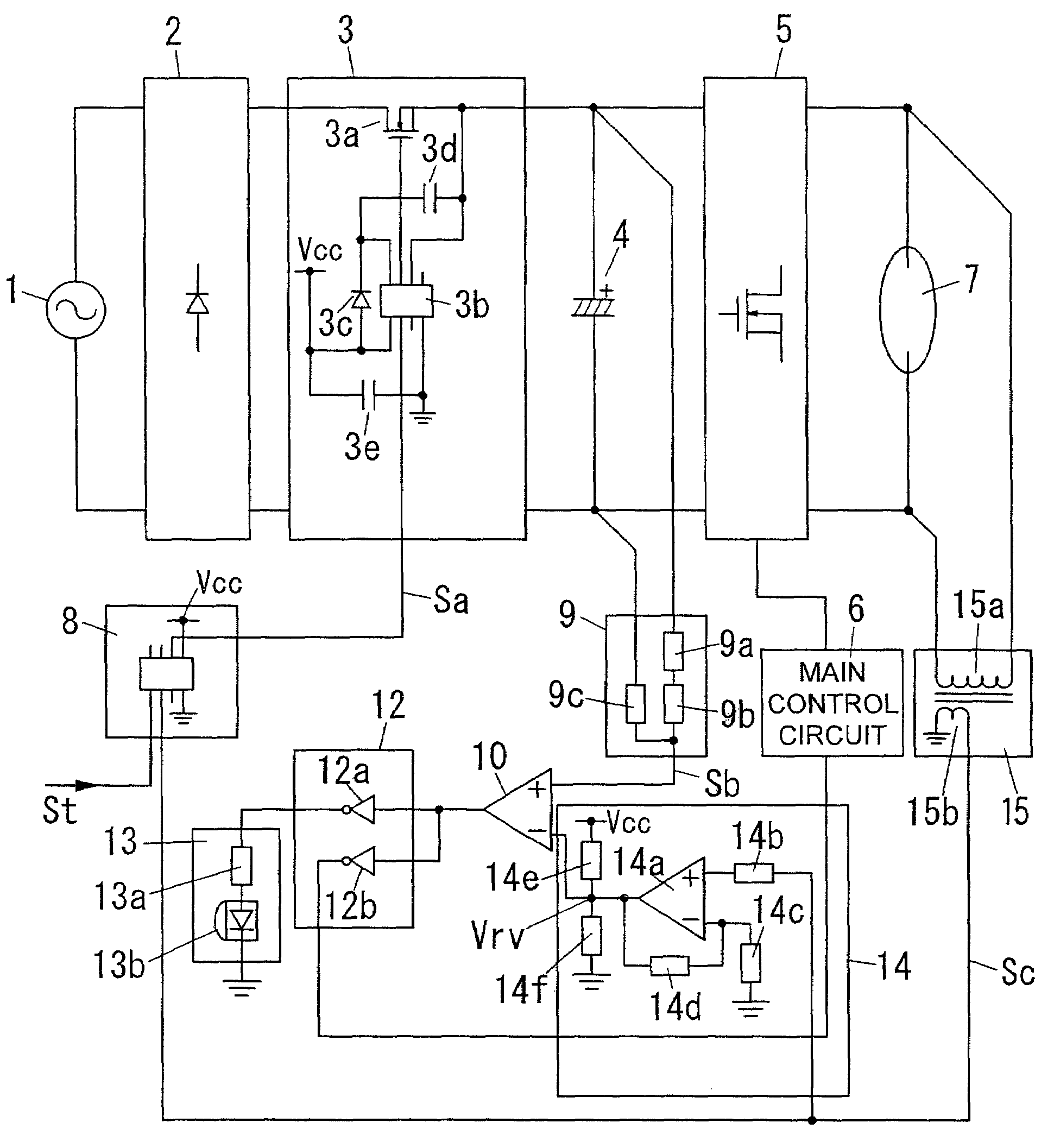
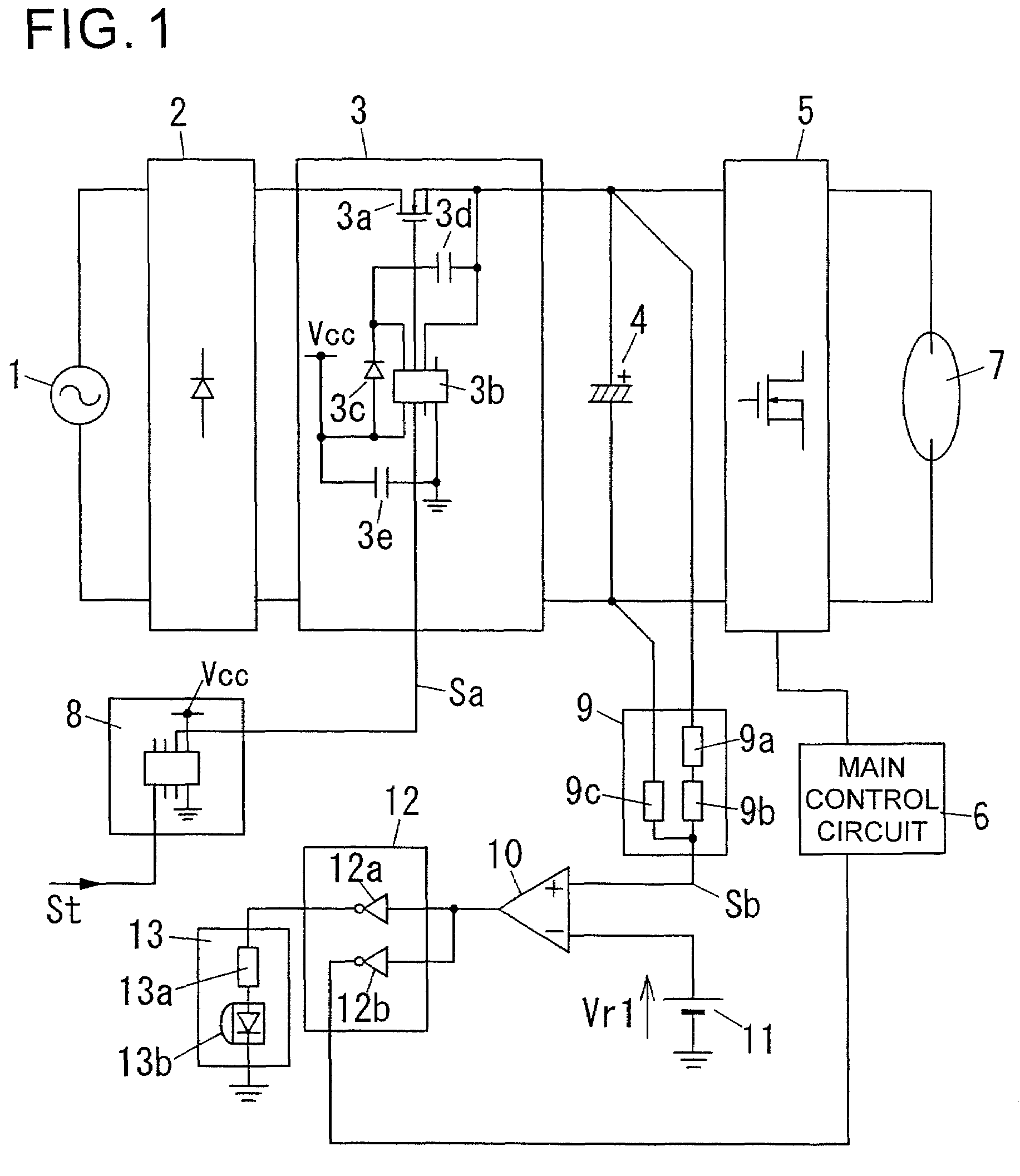
[0048]FIG. 1 shows a circuit configuration of a lighting device according to a first embodiment of the present invention. As shown in FIG. 1, this lighting device comprises a commercial power source 1, a rectifier 2, a power supply / shutoff section 3, a smoothing capacitor 4, an inverter main circuit 5, a main control circuit 6, a discharge lamp 7, a timer circuit 8, a capacitor-voltage detection circuit 9, a comparator 10, a reference voltage source 11, an auxiliary control circuit 12, and an indicator circuit 13.
[0049]An AC power supplied from the commercial power source 1 is rectified to a DC power by the rectifier 2. The DC power is input to the smoothing capacitor 4 through the power supply / shutoff section 3, and smoothed by the smoothing capacitor 4. The smoothed DC power is converted to an AC power by the inverter main circuit 5, and the AC power is supplied to the discharge lamp 7. In this process, the main control circuit 6 is operable to control an operation of the inverter...
second embodiment
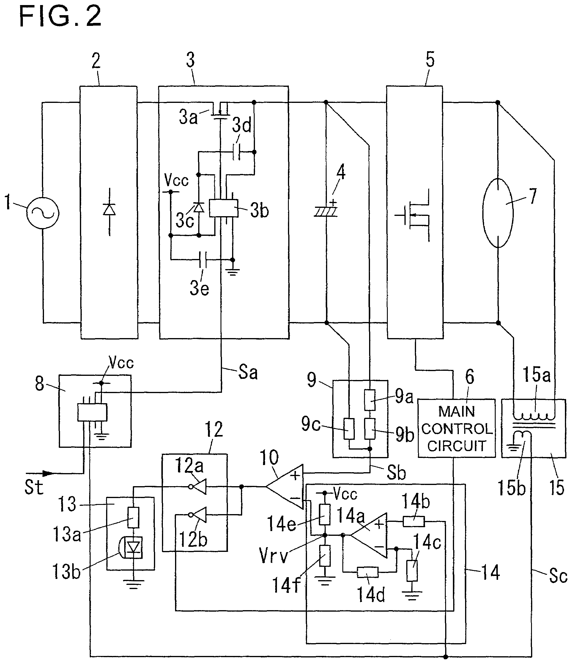
[0062]With reference to FIG. 2, a second embodiment of the present invention will be described below. FIG. 2 shows a circuit configuration of a lighting device according to the second embodiment. The lighting device according to the second embodiment is different from the lighting device according to the first embodiment only in the following points. A first difference is that a reference voltage generation circuit 14 is provided in place of the reference voltage source 11. A second difference is that a transformer having a primary winding 15a connected in parallel to a discharge lamp 7 and a secondary winding 15b magnetically coupled to the primary winding 15a is provided. The remaining configuration is the same as that of the lighting device according to the first embodiment. Thus, for avoiding duplication of description, the same element or component as that in the first embodiment is defined by the same reference numeral or code, and its description will be omitted.
[0063]The ref...
third embodiment
[0070]With reference to FIG. 3, a third embodiment of the present invention will be described below. FIG. 3 shows a circuit configuration of a lighting device according to the third embodiment. The lighting device according to the third embodiment is different from the lighting device according to the second embodiment only in the following points. A first difference is that a comparator 16 for determining a life end of a discharge lamp 7, and resistors 17a, 17b for dividing a control power source Vcc to generate a reference voltage Vr4, are provided. A second difference is that an auxiliary control circuit 12 and an indicator circuit 13 are different in configuration from those in the second embodiment. The remaining configuration is the same as that of the lighting device according to the second embodiment. Thus, for avoiding duplication of description, the same element or component as that in the second embodiment is defined by the same reference numeral or code, and its descript...
PUM
 Abstract
Description
Claims
Application Information
 - R&D
- Intellectual Property
- Life Sciences
- Materials
- Tech Scout
- Unparalleled Data Quality
- Higher Quality Content
- 60% Fewer Hallucinations
Browse by: Latest US Patents, China's latest patents, Technical Efficacy Thesaurus, Application Domain, Technology Topic, Popular Technical Reports.
© 2025 PatSnap. All rights reserved.Legal|Privacy policy|Modern Slavery Act Transparency Statement|Sitemap|About US| Contact US: help@patsnap.com


