Charging device

a charging device and secondary battery technology, applied in the direction of charging equalisation circuit, transportation and packaging, battery arrangement for several simultaneous batteries, etc., can solve the problems of battery performance not being fully realized, battery performance decline, and impeded charging progress, etc., to achieve a well balanced and suppressed voltage variation

Inactive Publication Date: 2009-07-07
NTT FACILITIES INC +1
View PDF13 Cites 18 Cited by
  • Summary
  • Abstract
  • Description
  • Claims
  • Application Information

AI Technical Summary

Benefits of technology

[0010]The present invention was made in consideration of the aforementioned circumstances. Its object is to provide a charging device for secondary batteries where, in an assembled battery having plural secondary batteries serially connected, it is possible to suppress voltage variations among the respective secondary batteries, and to perform charging in a well balanced manner.

Problems solved by technology

Such variations grow as the duration of service lengthens and as battery deterioration progresses, and are manifested in voltage disparities or the like.
This is because, when charging is performed at high voltage and discharge is performed at low voltage, the electrode material and electrolytes forming the secondary battery undergo chemical reaction, and secondary-battery performance declines.
Yet, with this method, there is the major drawback that the progress of charging is impeded, and battery performance cannot be fully realized.
However, merely by the simple attachment of a cell voltage suppression part, differences will occur in the charged state of each battery when performing recuperative charging after discharge if the internal states of the respective batteries differ.
As a result, under circumstances where a constant charging current is flowing, there are the problems that even if the charging of a certain battery is complete, other batteries are in the process of being charged, that the bypass current for voltage suppression is a high value, that part size is large, that the price is high, for example.
Thus, this method has not reached the stage of practical use.

Method used


Image

  • Charging device
  • Charging device
  • Charging device

Examples


Embodiment Construction

[0024]Suitable embodiments of the present invention are described below with reference to drawings. However, the present invention is not limited by any of the following embodiments, and, for example, the constituent elements of these embodiments may be appropriately combined.

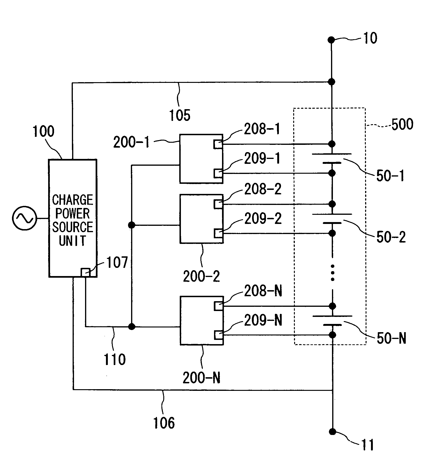
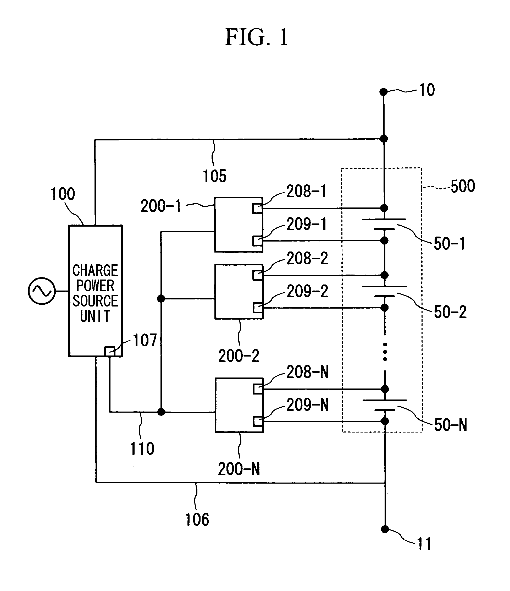
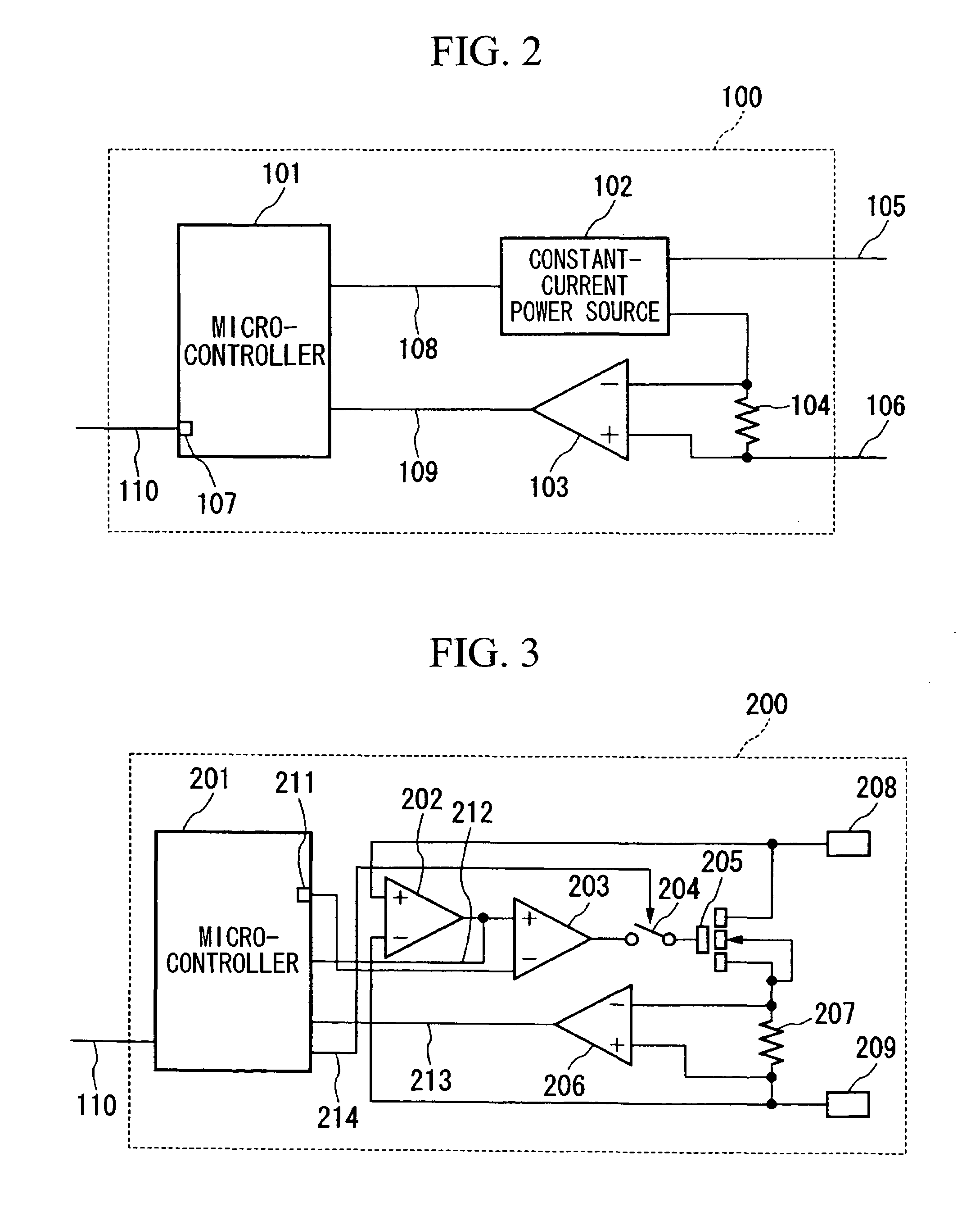
[0025]An embodiment of the present invention will be described as follows with reference to drawings. FIG. 1 is a block diagram showing the configuration of a charging device according to one embodiment of the present invention. FIG. 2 is a block diagram showing the configuration of a charge power source unit 100 shown in FIG. 1. FIG. 3 is a block diagram showing the configuration of charge controllers 200-1, 200-2, . . . , and 200-N shown in FIG. 1. FIG. 4 and FIG. 5 are respectively block diagrams showing examples of configuration of a power source system that applies the charging device of the present embodiment. FIG. 4 is a diagram that shows a common power source system for communications that supplies dir...


PUM


Abstract

A charging device including an assembled battery having plural secondary batteries serially connected, a charge power source unit which supplies charging current to both ends of said assembled battery having plural secondary batteries serially connected, and plural charge controllers which connect to both ends of each secondary battery among said plural secondary batteries; wherein said charge power source unit includes a charging current output unit which outputs charging current to said assembled battery, and a control unit which controls the current of said charging current output unit based on notification of the bypass current from said charge controllers; and wherein each of said plural charge controllers includes a current control unit which bypasses the current that flows to said secondary battery when the terminal voltage of said secondary battery has reached a preset voltage value, and a notification unit which notifies the control unit of said charge power source unit of said bypass current.

Description

CROSS-REFERENCE TO RELATED APPLICATION[0001]This application claims priority based on International Patent Application No. PCT / JP2004 / 012900, entitled “CHARGING DEVICE” by Shinya TAKAGI, Toshio MATSUSHIMA, Kazuo TSUKAMOTO, and Takuya SUDO, which claims priority of Japanese Application No. 2003-368952, filed on Oct. 29, 2003, and which was not published in English.[0002]Priority is claimed on Japanese Patent Application No. 2003-368952, filed Oct. 29, 2003, the content of which is incorporated herein by reference.TECHNICAL FIELD[0003]The present invention relates to a charging device for secondary batteries that performs well balanced charging of each secondary battery in an assembled battery having plural secondary batteries serially connected.BACKGROUND ART[0004]In various applications beginning with back-up power sources and the like for communication apparatuses, plural secondary batteries are serially connected and used as assembled batteries. However, even just after manufactur...

Claims


Application Information

Patent Timeline
Patent Type & Authority Patents(United States)
IPC IPC(8): H02J7/00H02J7/02
CPCH02J7/0016H02J7/04
Inventor TAKAGI, SHINYAMATSUSHIMA, TOSHIOTSUKAMOTO, KAZUOSUDO, TAKUYA
Owner NTT FACILITIES INC
Why Eureka
Try Eureka