Apparatus for wideband transmission conversion from coplanar waveguide to parallel transmission line

a technology of parallel transmission line and coplanar waveguide, which is applied in the direction of electrical apparatus, multiple-port network, waveguide, etc., can solve the problems that the technique of connecting cpw to parallel transmission line is not proposed, and the cpw cannot be stably adhered, so as to achieve less insertion loss and less return loss

Active Publication Date: 2009-07-07
SAMSUNG ELECTRONICS CO LTD
View PDF2 Cites 0 Cited by
  • Summary
  • Abstract
  • Description
  • Claims
  • Application Information

AI Technical Summary

Benefits of technology

[0011]It is yet another object of the present invention to provide a technique of connecting a CPW to a parallel transmission which has a less insertion loss and a less return loss.

Problems solved by technology

However, a connection structure shown in FIG. 2 is disadvantageous in that an area of the ground line is large so that it occupies a large space and a transmission line of the microstrip and a transmission line of the CPW cannot be stably adhered to each other.
However, a technique of connecting the CPW to the parallel transmission line was not proposed in the related art.

Method used


Image

  • Apparatus for wideband transmission conversion from coplanar waveguide to parallel transmission line
  • Apparatus for wideband transmission conversion from coplanar waveguide to parallel transmission line
  • Apparatus for wideband transmission conversion from coplanar waveguide to parallel transmission line

Examples


Embodiment Construction

[0025]Hereinafter, a technique of connecting a parallel transmission line to a CPW proposed by the present invention will be described in detail with reference to accompanying drawings.

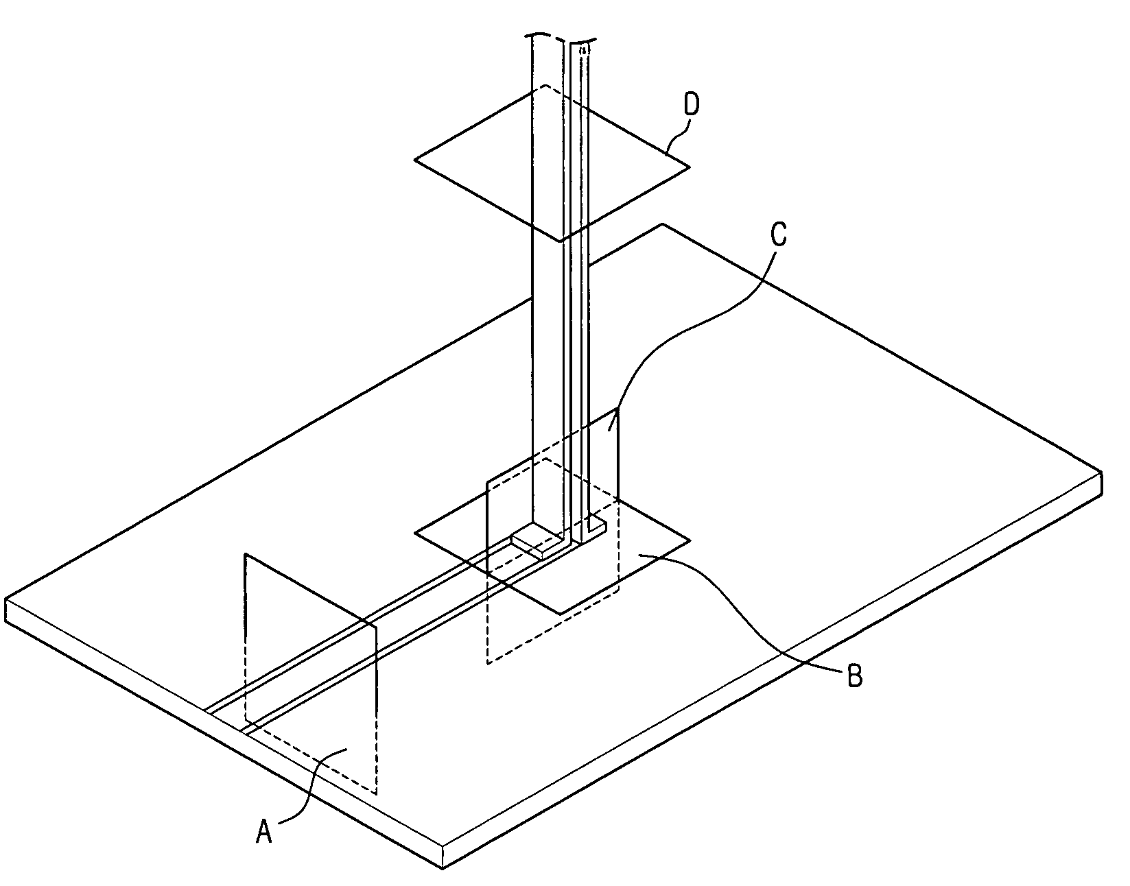
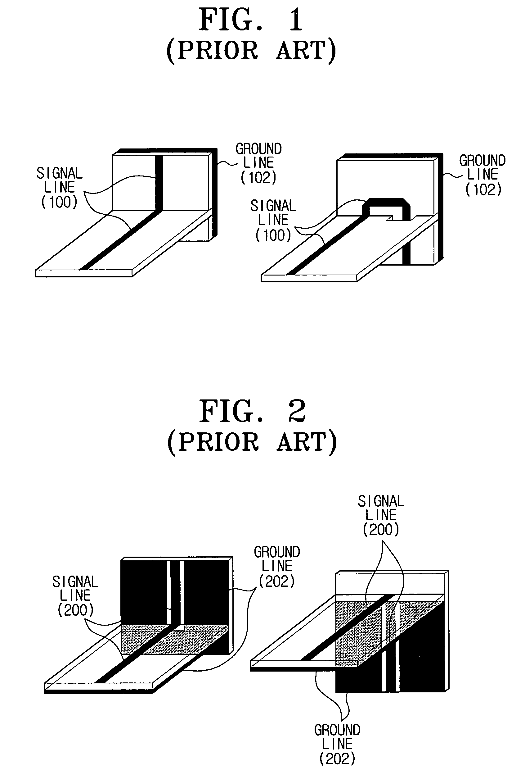
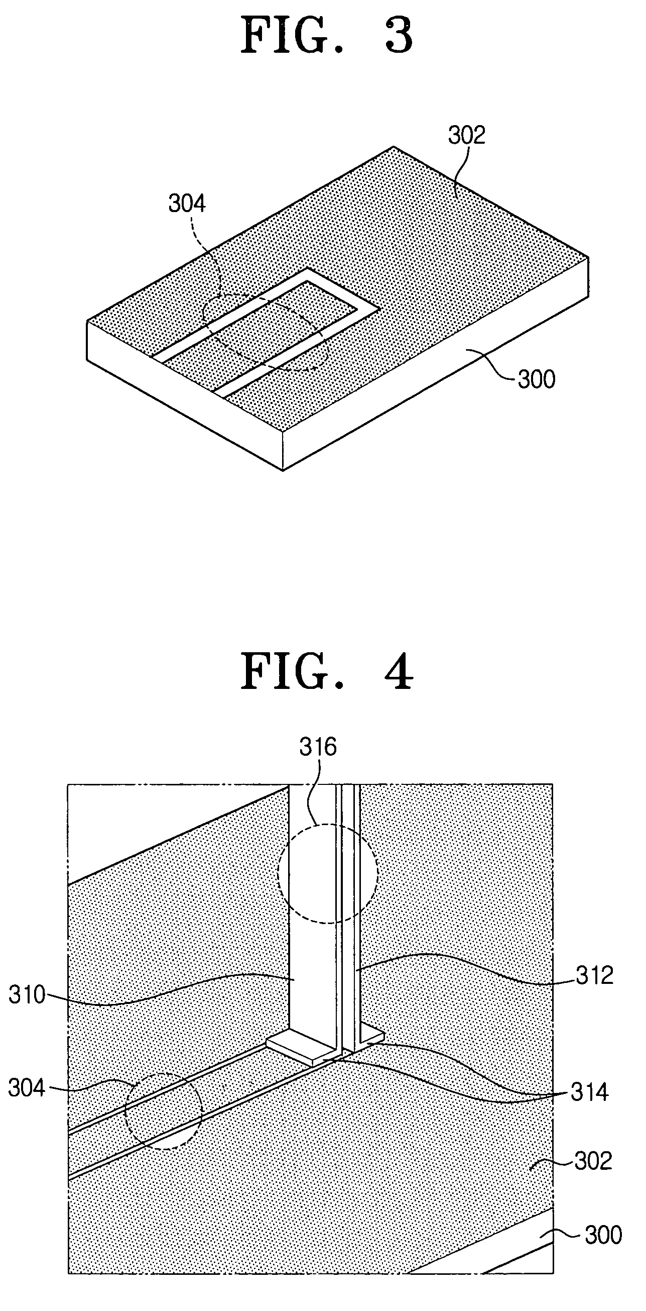
[0026]FIG. 3 shows a CPW associated with an exemplary embodiment of the present invention. The CPW allows one surface of a substrate 300 to be coated by a metal layer 302. In addition, a portion of the metal layer 302 is removed in order to discriminate a ground line from a signal line for transmitting a signal. Referring to FIG. 3, the metal layer 302 is removed like a “⊃” shape to discriminate the ground line from the signal line. That is, the ground line is shaped to surround the signal line, and the CPW is an unbalanced transmission line in which a shape of the ground line is not the same as the signal line.

[0027]FIG. 4 is a view illustrating a connection structure of connecting a parallel transmission line to a CPW in accordance with an exemplary embodiment of the present invention.

[0028]FIG. 4 s...


PUM


Abstract

A transmission line conversion apparatus connecting a parallel transmission line to a coplanar waveguide (CPW) is provided. To this end, the CPW including a transmission line composed of a signal line and a ground line which is formed on one surface of a dielectric substrate, and a parallel transmission line connected to the CPW, at a predetermined angle with respect to a substrate constituting the CPW, and composed of a signal line and a ground line, are proposed. In addition, the signal line of the CPW and the signal line of the parallel transmission line are connected to each other, and the ground line of the CPW and the ground line of the parallel transmission line are connected to each other. As such, by connecting the CPW to the parallel transmission line, a return loss can be minimized.

Description

CROSS-REFERENCE TO RELATED APPLICATIONS[0001]This application claims priority under 35 U.S.C. § 119 from Korean Patent Application No. 10-2005-0015724 filed on Feb. 25, 2005 in the Korean Intellectual Property Office, the entire content of which is incorporated herein by reference.BACKGROUND OF THE INVENTION[0002]1. Field of the Invention[0003]Apparatuses consistent with the present invention relate to a wideband transmission line conversion technique of connecting a coplanar waveguide (CPW) to a parallel transmission line having a predetermined angle from a substrate.[0004]2. Description of the Related Art[0005]Many techniques for connecting a microstrip to another microstrip have been proposed in the related art. FIG. 1 shows the conventional case of connecting a microstrip to another microstrip. Hereinafter, a signal line and a ground line will be collectively referred to as a transmission line for simplicity of description. The signal line 100 and the ground line 102 of two micr...

Claims


Application Information

Patent Timeline
Patent Type & Authority Patents(United States)
IPC IPC(8): H01P5/00
CPCH01P5/10H01P5/107
Inventor KWON, DO-HOONKIM, YONG-JINKIM, YOUNG-EILMOON, YOUNG-MIN
Owner SAMSUNG ELECTRONICS CO LTD
Why Eureka
Try Eureka