Microwave and radio frequency (RF) power electronics system having power combiner circuit

a technology of power electronics and combiner circuit, which is applied in the field of radio frequency and microwave power electronics systems, can solve the problems of increasing bandwidth, substantial power output dissipation between input and output ports, and not being suitable for many uses, so as to improve frequency response, reduce insertion loss, and reduce insertion loss

Active Publication Date: 2021-09-09
OPHIR RF
View PDF1 Cites 0 Cited by
  • Summary
  • Abstract
  • Description
  • Claims
  • Application Information

AI Technical Summary

Benefits of technology

The present invention provides a power combiner circuit that matches the load impedance at the output port with the impedance seen by each input port. The circuit achieves this match across an entire network topology, and is applicable and expandable to an unlimited number of power amplifier input circuits. The circuit has a very low return loss between input ports, regardless of the number of circuits. It also allows for the calculation of impedance for operation between particular frequencies to achieve reliable broadband performance. In the design, the impedance mismatch between input and output ports is reduced, and the insertion loss is reduced as compared to conventional power combiners. The circuit is a four-stage design, where each power amplifier branch represents a matching stage, and the output signal of each amplifier travels all the way to the load. The insertion loss is then distributed along the way to the output port, resulting in improved frequency response and reduced insertion loss.

Problems solved by technology

The Wilkinson topology at its simplest level typically includes an isolation resistor between power inputs that allows for combining (or dividing) input signals to provide an in-phase output signal, but is not suitable for many uses, in part because of a limited bandwidth capacity due to the use of quarter wavelength transmission lines.
The Wilkinson topology also results in substantial power output dissipation between input and output ports when higher bandwidth capacity is achieved due to the use of multiple quarter wavelength transmission lines.
If only one pair of quarter wavelength transmission lines are used, the bandwidth is limited to typically 30% of the design frequency, multiple pairs increase the bandwidth but also increase the power output dissipation.
This limits its achievable frequency bandwidth however, since no multiple sections can be used.
Additionally, a Darwish combiner does not allow for the load impedance at the output port to be matched to the impedance seen at the input ports, which leads to unwanted amplifier behavior when the network is used as a combiner.
The unwanted behavior can be manifested as unstable amplifier operation, loss in output power, overheating, and eventually amplifier (transistor) destruction.
The broadband capacity of many power combining schemes is limited due at least in part to practical considerations in transmission line length and power dissipation that inhibit a high-frequency response.
For example, if 1 dB of response loss is experienced in each stage, by the time the design is scaled to a three-stage combiner, substantial output power has been lost.

Method used


Image

  • Microwave and radio frequency (RF) power electronics system having power combiner circuit
  • Microwave and radio frequency (RF) power electronics system having power combiner circuit
  • Microwave and radio frequency (RF) power electronics system having power combiner circuit

Examples


Embodiment Construction

[0025]In the following description of the present invention reference is made to the exemplary embodiments illustrating the principles of the present invention and how it is practiced. Other embodiments will be utilized to practice the present invention and structural and functional changes will be made thereto without departing from the scope of the present invention.

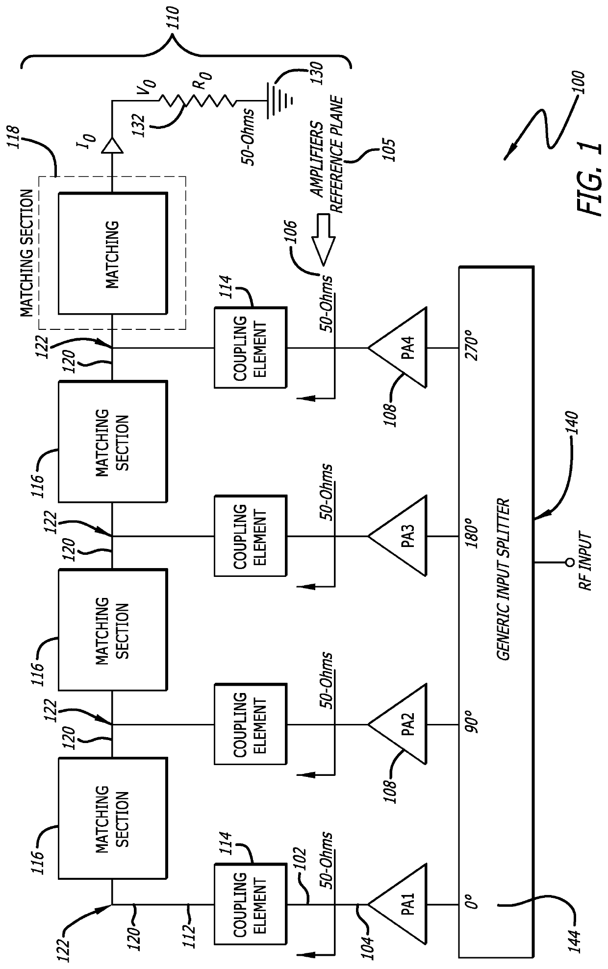
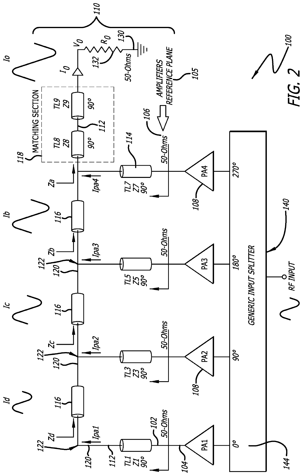
[0026]FIG. 1 is a circuit diagram of a power combiner circuit 100 according to the present invention, for power applications in radio frequency and microwave circuit design. In the power combiner circuit 100 described herein, input signals 104 are combined in an impedance matching network topology 110 that ensures that a load impedance 132 seen at an output port 130 is the same as the impedances 106 seen by each incoming input signal 104 at each input port 102. The power combiner circuit 100 includes several components that introduce a characteristic impedance in transmission lines 112, each of which contribute to enab...


PUM


Abstract

A power combiner circuit comprises a network topology for broadband RF and microwave systems that includes coupling elements, internodal matching sections, and an output matching section. The network topology serves as a combining mechanism for power from multiple power amplifiers. The network topology is designed so that characteristic impedances of transmissions lines serving as the coupling elements, internodal matching sections, and an output matching section produce a load impedance at an output port that is matched to the impedances seen by each power amplifier providing power to the power combiner circuit. Such a network topology is scalable to an unlimited number of power amplifiers, and enables a desired broadband frequency response for power amplification, while realizing a very low level of power output loss between input and output ports.

Description

CROSS-REFERENCE TO RELATED PATENT APPLICATION(S)[0001]This patent application claims priority to, and is a continuation of, U.S. non-provisional application Ser. No. 16 / 531,058, filed on Aug. 3, 2019, the contents of which are incorporated in their entirety herein. In accordance with 37 C.F.R. § 1.76, a claim of priority is included in an Application Data Sheet filed concurrently herewith.FIELD OF THE INVENTION[0002]The present invention relates to radio frequency and microwave power electronics systems. Specifically, the present invention relates to a power combiner circuit that is not constrained as to the number of ports, and exhibits very low power loss in combining power amplifier systems as well as performance increases for use in wide-bandwidth or broadband applications.BACKGROUND OF THE INVENTION[0003]Power combiner circuits are commonly used to combine signals from multiple power amplifiers and other integrated circuits in electronic circuit design. A combiner circuit combi...

Claims


Application Information

Patent Timeline
Patent Type & Authority Applications(United States)
IPC IPC(8): H03F3/60H03F3/21H03H7/46H01P5/10H03H7/38H01P3/06
CPCH03F3/60H03F3/21H01P3/06H01P5/10H03H7/38H03H7/463H01P5/12H03H7/48H03F3/605H03F3/602H03F2200/451H03F1/56H03F3/245H03F2200/318
Inventor BELTRAN, RAMON A.WANG, FEIYUVILLAGRANA, GREGORIO
Owner OPHIR RF
Why Eureka
Try Eureka