
Header for an electronic or opto-electronic component and process for manufacturing of such

a technology of opto-electronic components and headers, which is applied in the direction of lasers, electrical devices, laser details, etc., can solve the problems of high insertion loss, inability to precisely control the pin position in the opening, and fixed position of the pedestal with respect to the respective opening, etc., to achieve tight and close connection, small brazing bulge, and high thermal conductivity

Pending Publication Date: 2022-03-03
SCHOTT AG
View PDF0 Cites 2 Cited by
  • Summary
  • Abstract
  • Description
  • Claims
  • Application Information

AI Technical Summary

Benefits of technology

The present invention provides a header which is designed to mount electronic or optoelectronic components with low insertion loss. This header has optimized offsets which allow for improved performance and reduced signal loss, resulting in a greater signal bandwidth. The manufacturing process for this header is also provided.

Problems solved by technology

A drawback of state-of the art headers is that the position of the pedestal with respect to the respective opening is fixed.
However, the pin position in the opening cannot be controlled precisely, varying between a maximum position and a minimum position.
However, as a drawback, such a large distance between pin and submount will result in a high insertion loss.
However, the distance between opening and pedestal may not be minimized, as this might result in too small a distance between the pedestal and the pin to arrange the submount in between the both in case the pin is in the minimum position.
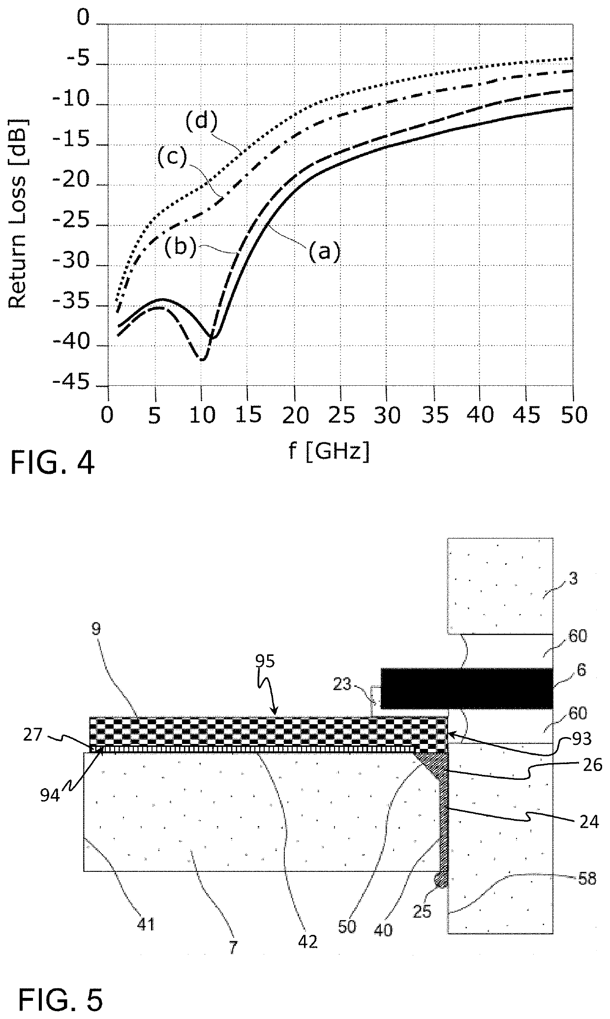
This results in a smaller insertion loss of the packaged electronic, in particular opto-electronic, component, as the offset between the submount surface and the pin may be set in a narrow range.
In this way, only a very small amount of excess brazing material may be produced, resulting in only a small brazing bulge.

Method used


Image

  • Header for an electronic or opto-electronic component and process for manufacturing of such
  • Header for an electronic or opto-electronic component and process for manufacturing of such
  • Header for an electronic or opto-electronic component and process for manufacturing of such

Examples


Embodiment Construction

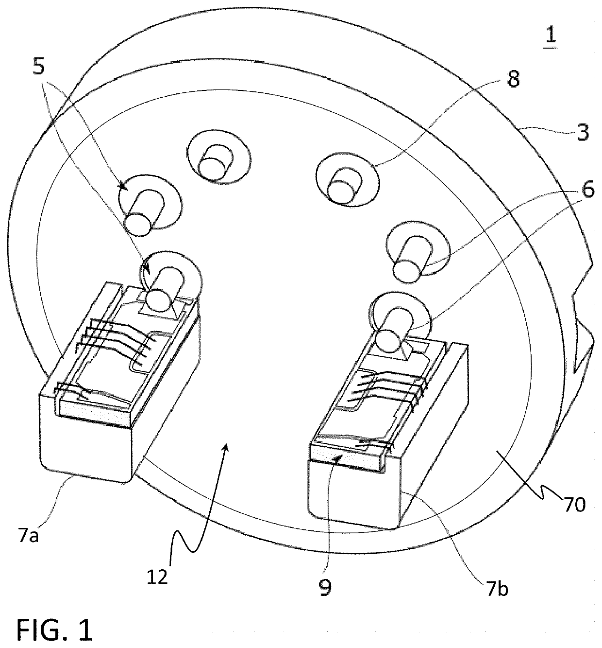
[0034]FIG. 1 is a perspective side view of a header 1 according to an embodiment.

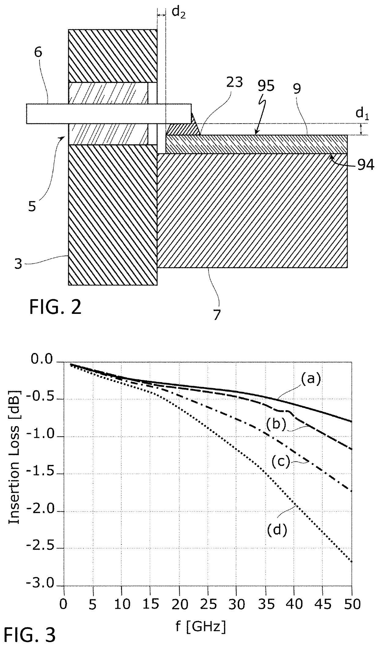
[0035]The header 1 as shown in FIG. 1 comprises a base 3 with two or more electrical feedthroughs 5. The feedthroughs 5 serve to transmit electrical signals in or out of the header 1. Each feedthrough 5 comprises a feedthrough pin 6 that extends through the base 3 and is electrically isolated from it. For this purpose, the base 3 comprises eyelets or openings 8 filled with an insulating material, preferably glass, in which the feedthrough pin 6 is fixed. Two pedestals 7a, 7b are connected to and protrude from the base 3. Generally, without being restricted to the embodiment as depicted in FIG. 1, the header 1 comprises at least one pedestal 7. However, it may be preferred to provide a header 1 with at least two pedestals 7a, 7b, for example for headers comprising laser chips, especially DML, as in many cases, laser driver IC are driving the DML with differential signals, meaning that header 1 needs two ...


PUM


Abstract

A header for an electronic component is provided. The header includes a base, a pedestal, and a submount. The base has a feedthrough with a feedthrough pin extending through the base and being electrically insulated from the base. The pedestal is connected to the base. The submount is connected to the pedestal. The pedestal is joined to the base via a pedestal substance-to-substance bond.

Description

CROSS REFERENCE TO RELATED APPLICATIONS[0001]This application claims benefit under 35 USC § 119 of EP Application 20 194 347.9 filed Sep. 3, 2020, the entire contents of which are incorporated herein by reference.BACKGROUND1. Field of the Invention[0002]The invention relates in general to the packaging of electronic components. In particular, the invention relates to the design of a header, preferably a transistor outline (TO) header for mounting an electronic or opto-electronic device. The invention is particularly suitable for laser diodes as electronic or optoelectronic devices. However, the invention relates to electronic packaging for any electronic component in which a submount for being electrically connected to a feedthrough pin is arranged on and attached to a pedestal.2. Description of Related Art[0003]For some opto-electronic applications, the wavelengths of the beam emitted by the laser chip needs to be controlled precisely, as the wavelength of the laser is temperature ...

Claims


Application Information

Patent Timeline
IPC IPC(8): H01S5/023H01S5/02212
CPCH01S5/023H01S5/02415H01S5/02212H01S5/02345H01S5/0237H01L23/045
Inventor WAI LI, ONGTAN, JIAN DEANPING, AMY SOON LIKRAUSE, ANDREASAOWUDOMSUK, ARTITDROEGEMUELLER, KARSTEN
Owner SCHOTT AG
Learn More