Method for dynamically establishing logical link in PON systems and an optical network unit for the method

a technology of pon systems and optical networks, applied in data switching details, data switching networks, high-level techniques, etc., can solve the problems of waste of limited transmission bandwidth, waste of dba process performed for non-use of logical links, etc., to prevent unnecessary use of transmission bandwidth and reduce the waste of olt and onu processing capacity.

Active Publication Date: 2009-07-07
KDDI CORP
View PDF3 Cites 10 Cited by
  • Summary
  • Abstract
  • Description
  • Claims
  • Application Information

AI Technical Summary

Benefits of technology

[0014]An ONU according to an exemplary embodiment of the invention is a unit disposed at each subscriber's site in a PON system and includes first means to request an OLT of the PON system to assign its own logical link in response to a predetermined inquiry message received after the ONU is powered on, a start-up detector to detect start-up of a communication device connected to the ONU, and second means to request the OLT to assign a logical link for the communication device according to the start-up of the communication device. According to the exemplary embodiment, a logical link is established per application as the need arises and thus it prevents the unnecessary use of transmission bandwidths. In addition, the processing capacity of both OLT and ONU is no longer wasted in order to maintain logical links that are not in current use.

Problems solved by technology

Thus, the processes required for establishing logical links also become three times. Therefore, when a number of ONUs are powered on at the same time, it takes a quite long time until the whole ONUs complete the establishment of logical links.
As explained above, in conventional methods, it takes really long time for an ONU to become available because the ONU tries to establish the whole logical links to be used at once when the ONU is powered on.
In the three logical links, if there is a logical link that is not used, the DBA process performed for the nonuse logical link becomes useless and waste of limited transmission bandwidths.
Due to this useless DBA process, a load of the OLT is also increased.

Method used


Image

  • Method for dynamically establishing logical link in PON systems and an optical network unit for the method
  • Method for dynamically establishing logical link in PON systems and an optical network unit for the method
  • Method for dynamically establishing logical link in PON systems and an optical network unit for the method

Examples


Embodiment Construction

[0019]Explanatory embodiments of the invention are explained below in detail with reference to the drawings.

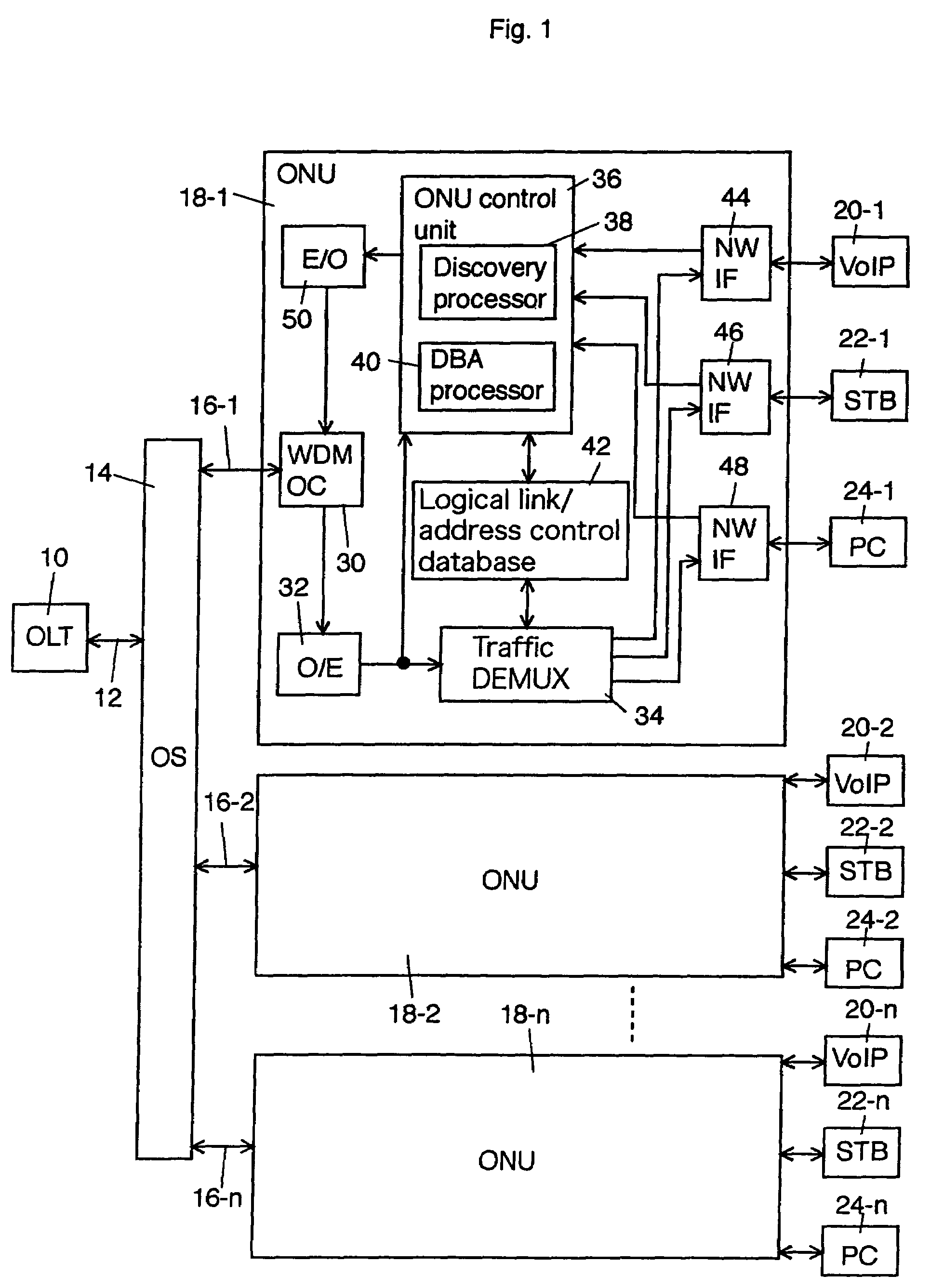
[0020]FIG. 1 shows a schematic block diagram according to an exemplary embodiment of the invention. An optical line terminal (OLT) 10, e.g. an optical terminal apparatus disposed at a center station connects to an optical splitter 14 through an optical fiber 12. The optical splitter 14 also connects to optical network units (ONUs) 18-1 to 18-n, e.g. optical terminal apparatuses at subscribers' sites through optical fibers 16-1 to 16-n respectively. The wavelength of a downstream signal light from the OLT 10 to the ONUs 18-1 to 18-n is 1.49 μm while the wavelength of an upstream signal light from the ONUs 18-1 to 18-n to the OLT 10 is 1.31 μm.

[0021]The optical splitter 14 is a passive optical element to split a downstream optical signal or a down traffic from the OLT 10 into n portions, outputs the split optical signals to the optical fibers 16-1 to 16-n respectively, and appli...


PUM


Abstract

The invention is applied to a PON system including an optical line terminal (OLT) at a center station, a plurality of optical network units (ONUs) at subscribers' sites, and an optical transmission line shared by the plurality ONUs to optically connect between the OLT and the plurality of ONUs. Each of the ONUs requests the OLT to assign a logical link according to start-up of an application.

Description

CROSS REFERENCE TO RELATED APPLICATIONS[0001]This application claims priority to Japanese Patent Application No. 2004-299598, filed on Oct. 14, 2004, the entire contents of which are incorporated herein by reference.FIELD OF THE INVENTION[0002]This invention relates to a method to dynamically establish logical link in PON (Passive Optical Network) systems and an optical network unit (ONU) apparatus used for the method.BACKGROUND OF THE INVENTION[0003]A PON system includes a configuration in which an OLT (Optical Line Terminal) and each subscriber's ONU (Optical network Unit) are connected with optical transmission lines made exclusively from passive optical elements. In other words, a 1:n optical splitter is disposed between an optical fiber connected to the OLT and a plurality of optical fibers respectively connected to the ONUs.[0004]In an E-PON (IEEE 802.3ah) system, which has been standardized in July, 2004, a logical link can be established on an optical transmission line using...

Claims


Application Information

Patent Timeline
Patent Type & Authority Patents(United States)
IPC IPC(8): H04J14/08
CPCH04L12/12Y02B60/34Y02D30/50
Inventor TANAKA, KEIJIEDAGAWA, NOBORU
Owner KDDI CORP
Why Eureka
Try Eureka