
Vehicle electrification using a clutched vibration damper

a technology of vibration damper and clutch, which is applied in the direction of engine starter, machine/engine, gearbox, etc., can solve the problems of inadequate power supply to the various accessories of the conventional drive system, inadequate conventional drive system, and inadequate conventional drive system

Inactive Publication Date: 2009-07-14
INT TRUCK INTPROP LLC
View PDF16 Cites 22 Cited by
  • Summary
  • Abstract
  • Description
  • Claims
  • Application Information

AI Technical Summary

Benefits of technology

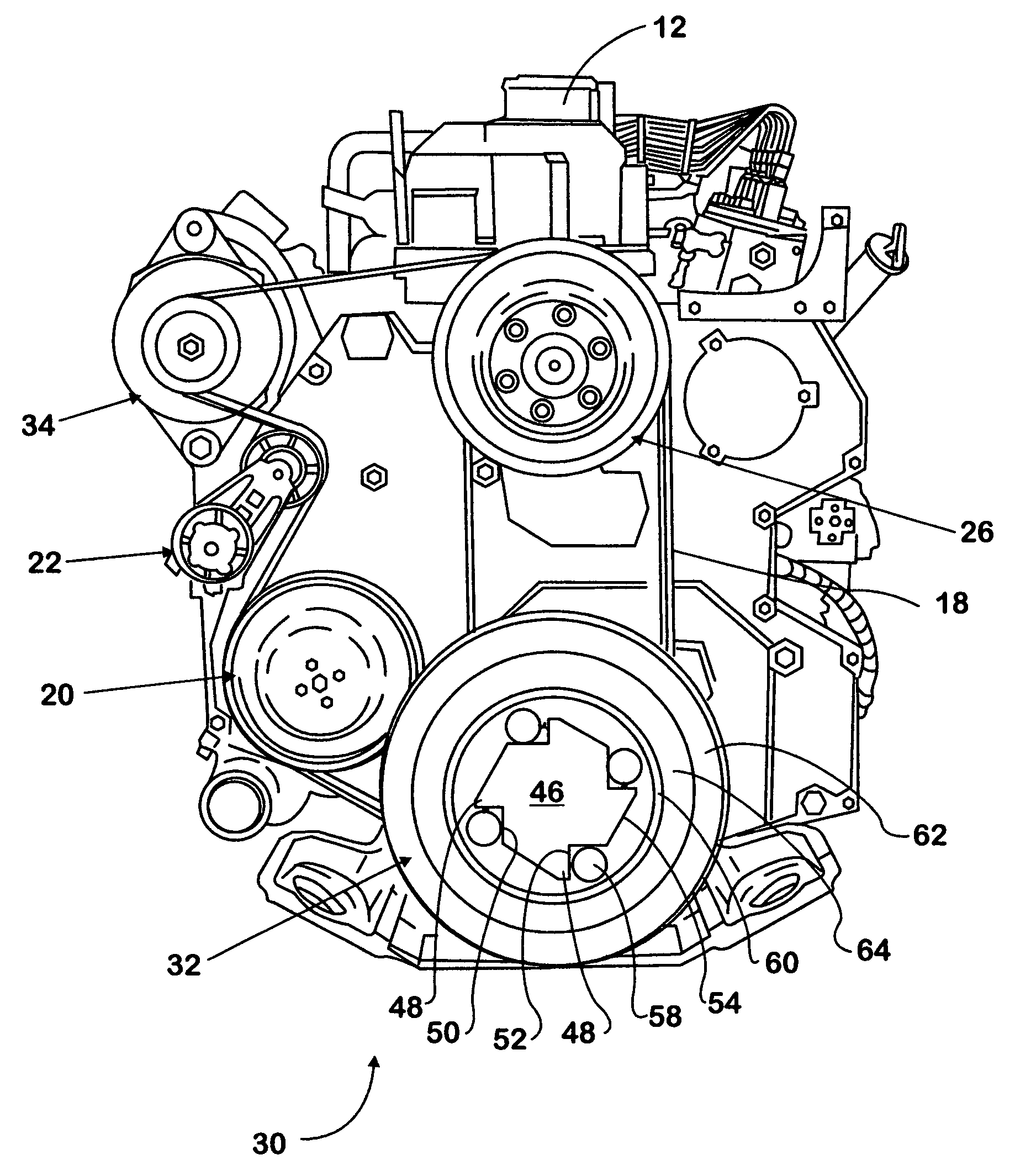
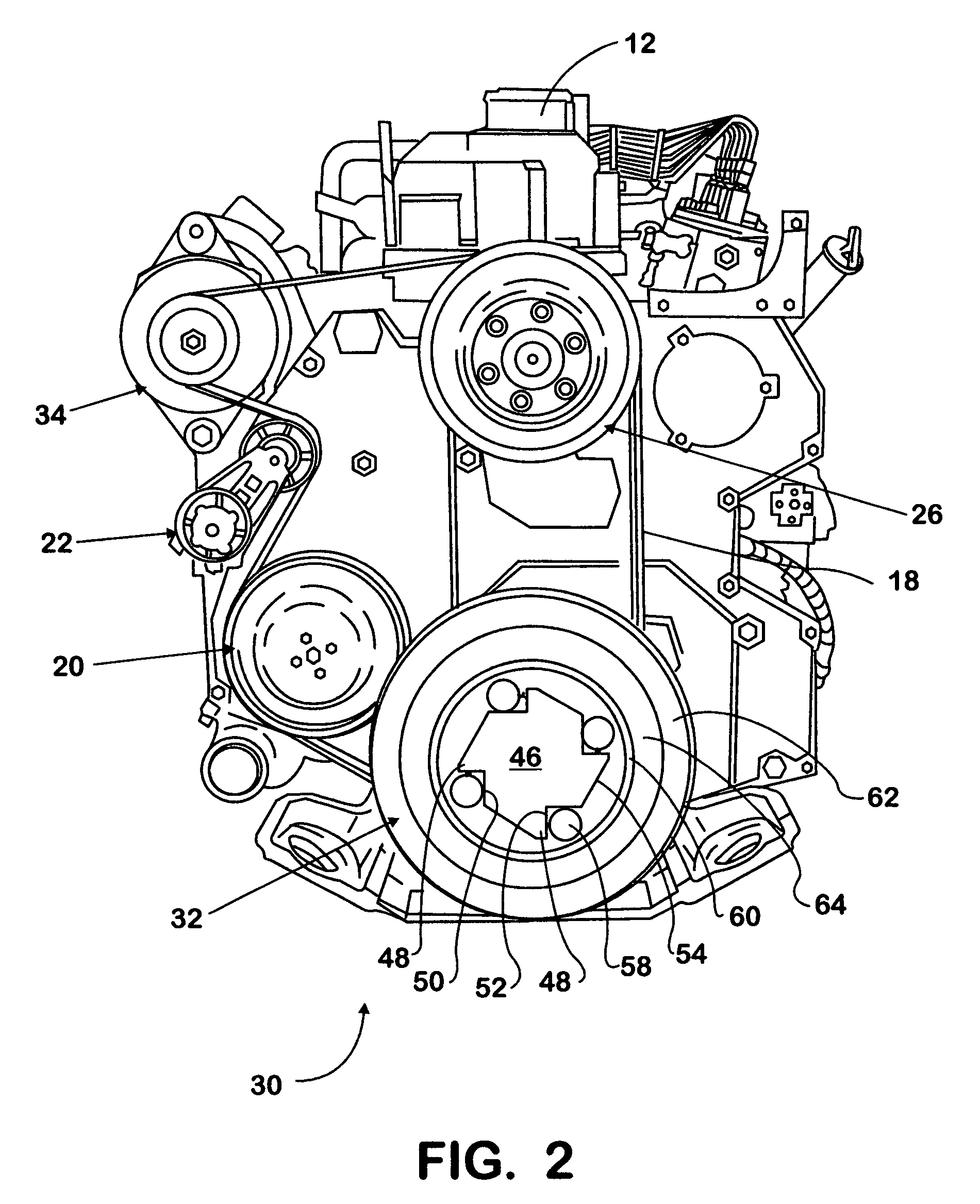
The present driving system of a motor vehicle provides power for both the vehicle's propulsion and accessories. It includes a one-way clutch vibration damper that allows for smooth operation and reduces vibrations. The system also includes a controller that can selectively provide more power to the motor / generator to exceed the torque produced by the engine. The driving system can alternately use the engine or the motor / generator for power, and the one-way clutch vibration damper ensures smooth operation in both modes.

Problems solved by technology

In many cases, the conventional drive system is inadequate to supply power to the various accessories.
One situation in which the conventional drive system is inadequate is when the vehicle is stationary.
A second situation in which the conventional drive system is inadequate is when the vehicle propulsion requires an extreme load on the engine, and the engine cannot provide adequate power to both propel the vehicle and power the accessories.
Under these circumstances, the loading applied to the engine for powering the accessories is called a “parasitic” loading because it can negatively impact the amount of power delivered for propulsion.

Method used


Image

  • Vehicle electrification using a clutched vibration damper
  • Vehicle electrification using a clutched vibration damper
  • Vehicle electrification using a clutched vibration damper

Examples


Embodiment Construction

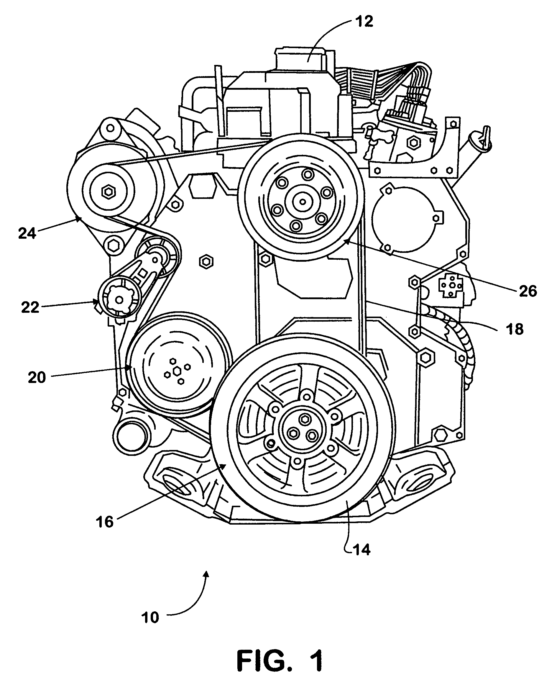
[0016]Referring now to FIG. 1, a prior art driving system assembly is depicted generally at 10, and is disposed on an engine 12. The drive system 10 is conventionally powered by torque from a pulley 14 mounted on the crankshaft (not shown) of the engine 12. A vibration damper 16 is typically implemented on the pulley 14 and connected to the crankshaft to lessen the torsional vibration between the crankshaft and the pulley 14. An accessory belt 18 mounted on the pulley 14 winds through the various accessories. In this particular engine 12, the accessory belt 18 extends from the pulley 14 to a water pump pulley 20, to a fan belt auto tensioner 22, to an alternator 24, to a fan drive pulley 26, and back to the vibration damper 16. It should be understood that the number, type and arrangement of the various accessories can be modified depending on the engine 12 and the vehicle.

[0017]In many cases the prior art driving system 10 is inadequate to fulfill the vehicle's accessory and propul...


PUM


Abstract

A driving system of a motor vehicle for providing vehicle propulsion power and accessory power includes an engine having an accessory belt providing power to at least one accessory machine and a motor / generator operatively connected to the accessory belt for alternately driving and being driven by the accessory belt. A one-way clutch vibration damper includes an engine input member and a belt interface. The input member is concentrically disposed with respect to the belt interface and is attached to an engine crankshaft for transmitting torque in a pre-determined direction. The belt interface rotates freely when torque applied by the motor / generator through the accessory belt is greater than the torque applied by the input member. The belt interface rotates at the same rotational speed as the input member when torque transmitted through the accessory belt is less than or in the opposite direction as the rotation of the input member.

Description

BACKGROUND OF THE INVENTION[0001]The present invention relates generally to power systems in vehicles. More specifically, the present invention relates to a power system having both a standard mode and an electrified mode to operate engine accessories.[0002]Automotive vehicles typically have a drive system for powering engine accessories such as alternators, water pumps, air conditioning compressors, power steering pumps, radiator cooling fans, etc. The drive system is powered by torque from a pulley mounted on the crankshaft on an engine. The crankshaft converts the reciprocal motion of the engine's pistons into a rotational motion, which in turn, rotates the pulley and drives an accessory belt. The accessory belt winds through the various engine accessories providing them with mechanical power.[0003]Powering the accessories is a secondary function of the engine, the primary function of the engine being providing power for propulsion. In many cases, the conventional drive system is...

Claims


Application Information

Patent Timeline
Patent Type & Authority Patents(United States)
IPC IPC(8): B60K17/28
CPCF02B67/06F16D41/07F02N15/006F02N11/04F02N15/022
Inventor PALLADINO, JAMES
Owner INT TRUCK INTPROP LLC
Learn More