
Transducer arrangement

a transducer and arrangement technology, applied in the direction of roads, roads, roads, etc., can solve the problems of removing the possibility of column blockage, adding an additional cost of a second external laser transmitter, and time to properly set up the second external laser transmitter

Inactive Publication Date: 2009-07-14
TRIMBLE NAVIGATION LTD
View PDF31 Cites 16 Cited by
  • Summary
  • Abstract
  • Description
  • Claims
  • Application Information

AI Technical Summary

Benefits of technology

[0005]In the laser transmitter arrangement, a projected rotating beam of laser light defines a reference plane. A pair of laser receivers, one receiver mounted at each end of the tool on an associated mast for vertical movement with the tool, detect the reference plane and a control system of the machine then actuates hydraulic valves to supply fluid to the hydraulic cylinders in response to this detected level. As a result, the elevation of each end of the tool can be precisely controlled. In the sonic pulse arrangement, as disclosed by U.S. Pat. No. 4,924,374 to Middleton, et al., a tool carried by a machine, can level a surface to a chosen depth by determining the time it takes for an acoustic pulse to travel from a transducer, such as an ultrasonic receiver, provided on a mast at each end of the tool to a reference surface and back. As a result, with this time value being used to calibrate a microprocessor-controlled distance-measuring device the elevation of each end of the tool can be precisely controlled. Accordingly, in both types of the above described arrangements, each of their respective type of receivers, either laser or sonic, provides elevational feedback to drive the hydraulics controlling the elevation of each side of the tool.
[0007]One approach to this problem, in the laser arrangement is to set up two external laser transmitters at the same elevation on opposite sides of the tool. In this way, if a column blocks one of the transmitters, the other external transmitter is likely to be illuminating the receivers at the ends of the tool, thereby compensating for the blockage. Essentially, the prior art method is to eliminate all blind spots around the receivers. However, this prior art method adds an additional cost of a second external transmitter and time to properly set up the second external laser transmitter to eliminate the possibility of a column block.

Problems solved by technology

A problem may arise, however, if one the receivers is blocked by something of an appreciable height, such as, for example, a support column in a building, in the case of the laser receiver or interrupted in the case of the ultrasonic receiver.
However, this prior art method adds an additional cost of a second external transmitter and time to properly set up the second external laser transmitter to eliminate the possibility of a column block.

Method used


Image

  • Transducer arrangement
  • Transducer arrangement
  • Transducer arrangement

Examples


Embodiment Construction

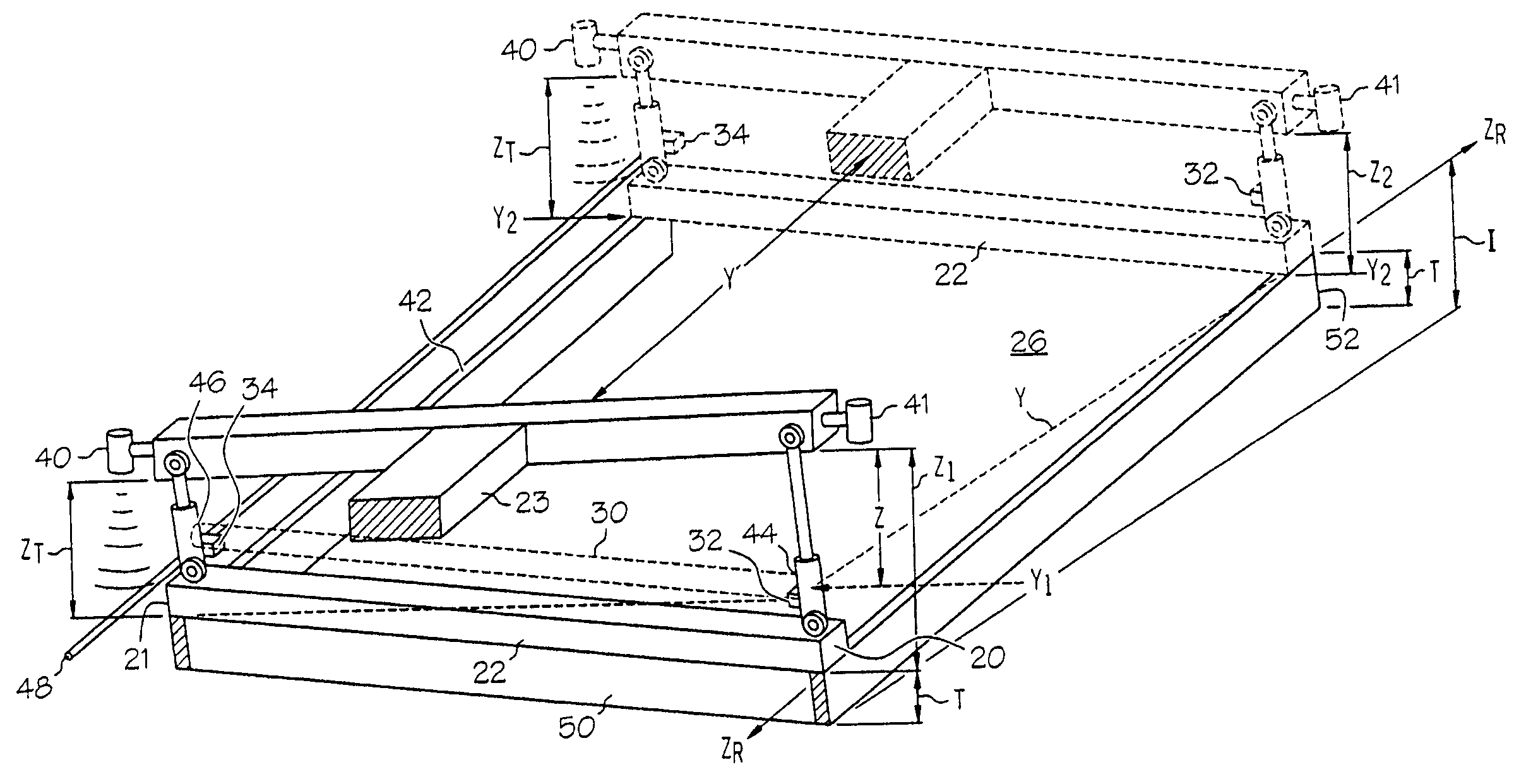
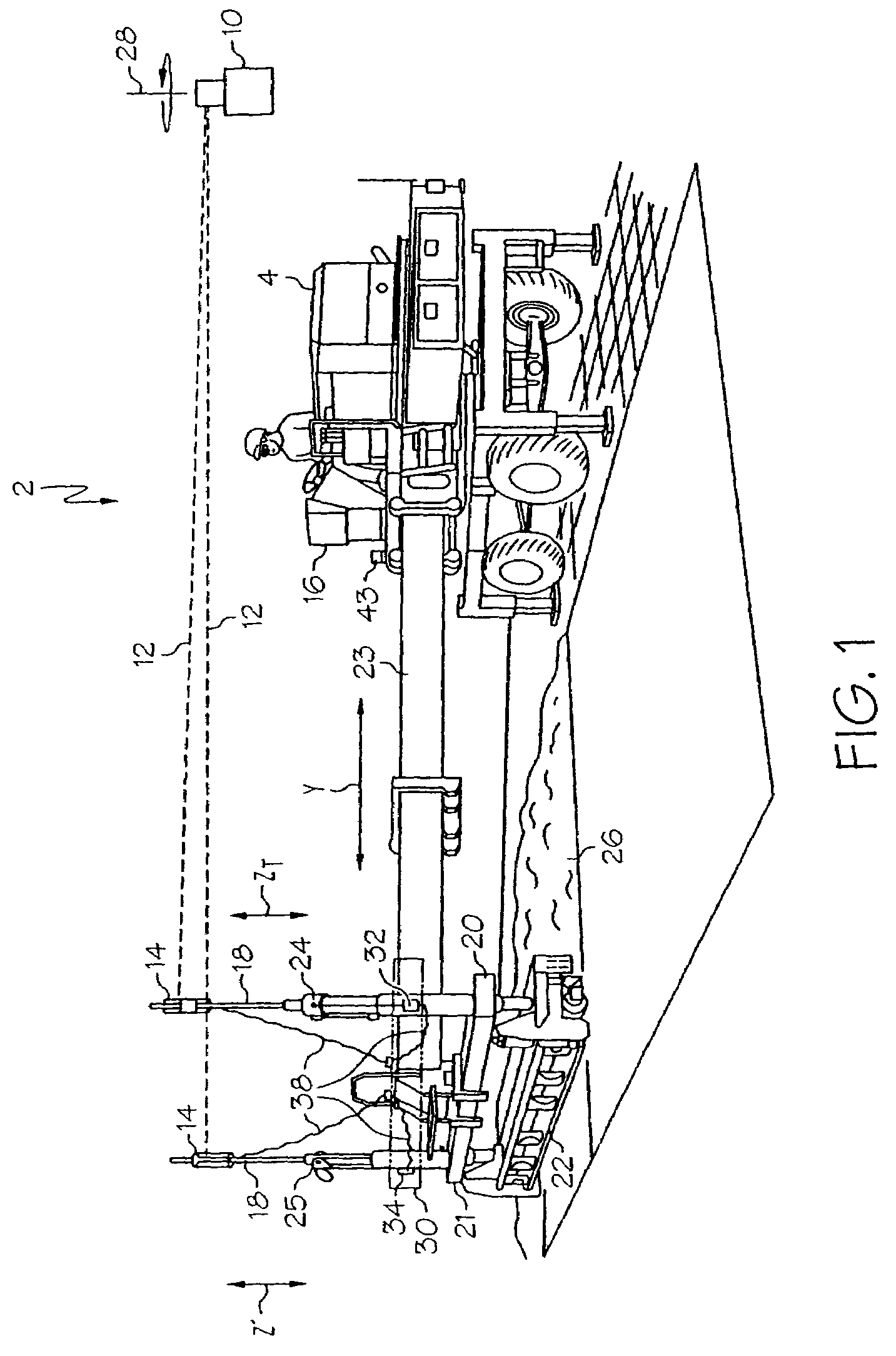
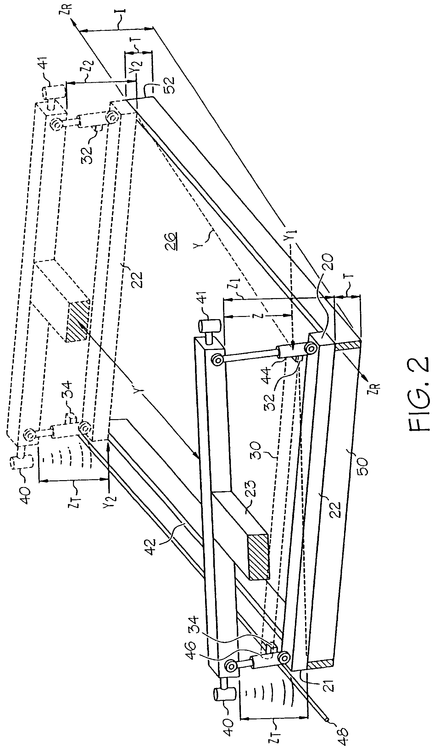
[0028]Referring to FIG. 1 of the drawings, the device implementing the preferred embodiment of invention herein is a conventional control system 2 for a machine, such as a concrete screed 4, that typically consist of an external laser transmitter 10, transmitting a rotating laser beam 12, in order to provide a reference, a pair of elevation receiver, such as laser receivers 14, and a control box 16 for controlling electro-hydraulic control values (not shown) of the concrete screed 4. The concrete screed 4 further includes a pair of masts 18, each carrying one of the pair of laser receivers 14, attached with and moved generally vertically, independently, with respective ends 20 and 21 of a tool or screed head 22. The screed head 22 is attached to the end of a hydraulic boom arm 23 which moves the screed head 22 in longitudinal direction Y. During normal operation, the control box 16 causes actuation of the hydraulic valves such that hydraulic cylinders 24 and 25 at the ends 20 and 21...


PUM


Abstract

A transducer arrangement and method that generates control signals indicating relative positions of the ends of a hydraulically movable tool of a machine. The generated control signals of the present invention are used by a conventional control circuit of the machine to control the ends of the hydraulically movable tool having elevation receivers as an desired mode of operation or when reception by one of the elevational receivers of a elevational reference, which provides an absolute position of the ends of the tool, is interrupted. The conventional control circuit of the machine uses the generated signal of the transducer arrangement of the present invention to maintain a relative elevation position of one side of the tool to the absolute position of the other side of the tool as desired or until both receiver can reacquire the elevational reference.

Description

CROSS-REFERENCE TO RELATED APPLICATIONS[0001]This application is a continuation-in-part of U.S. patent application Ser. No. 09 / 491,907, filed Jan. 27, 2000, which claims the benefit of U.S. Provisional Application No. 60 / 117,348, filed Jan. 27, 1999, both applications of which are incorporated herein by reference.BACKGROUND AND SUMMARY OF THE INVENTION[0002]The present invention relates to a linear transducer arrangement for control of a tool carried by a machine, and more specifically, to a control system of a hydraulically moveable tool carried by a machine having laser receivers receiving actual elevational positions of the ends of the tool from an external laser transmitter and a pair of linear transducer arrangement providing relative elevational positions of the ends of the tool to each other.[0003]In concrete paving operations, after concrete is poured it is commonly finished by drawing a tool, such as a screed head, over the surface of the contour to finish the surface of th...

Claims


Application Information

Patent Timeline
Patent Type & Authority Patents(United States)
IPC IPC(8): E01C19/22E01C19/00E02F3/84
CPCE02F3/847E01C19/004
Inventor ZACHMAN, MARK E.YOST, JERALD W.
Owner TRIMBLE NAVIGATION LTD
Learn More