

Current feed-through adaptive voltage position control for a voltage regulator
a voltage regulator and current feed-through technology, applied in the field of low gain current mode voltage regulators, can solve the problems of increasing the size and cost of the voltage regulator, damaging the load on the voltage regulator, and the method is only applicable to high gain voltage regulators, and achieves the effect of low gain
- Summary
- Abstract
- Description
- Claims
- Application Information
AI Technical Summary
Benefits of technology
Problems solved by technology
Method used
Image

Examples
first embodiment
[0024]FIG. 5 shows first embodiment according to the present invention, and FIG. 6 shows waveforms of various signals in the voltage regulator 400 of FIG. 5. In the current mode voltage regulator 400, switches SW1 and SW2 are coupled in series between input voltage PVDD and ground GND, SR latch 412 produces signals UG and LG in response to fixed-frequency clock CLK and PWM signal to switch the switches SW1 and SW2 with drivers 414 and 416, respectively, to produce inductor current IL flowing through inductor L to charge output capacitor C to thereby generate the output voltage Vout, error amplifier 402 of low gain M generates error signal COMP from the difference between the output voltage Vout and reference voltage Vref to provide for the non-inverting input of PWM comparator 410, transconductive amplifier 418 of gain K serves as current sense circuit whose two inputs are coupled to the two ends of sense resistor Rs coupled in series to the inductor L to sense the inductor current ...
second embodiment
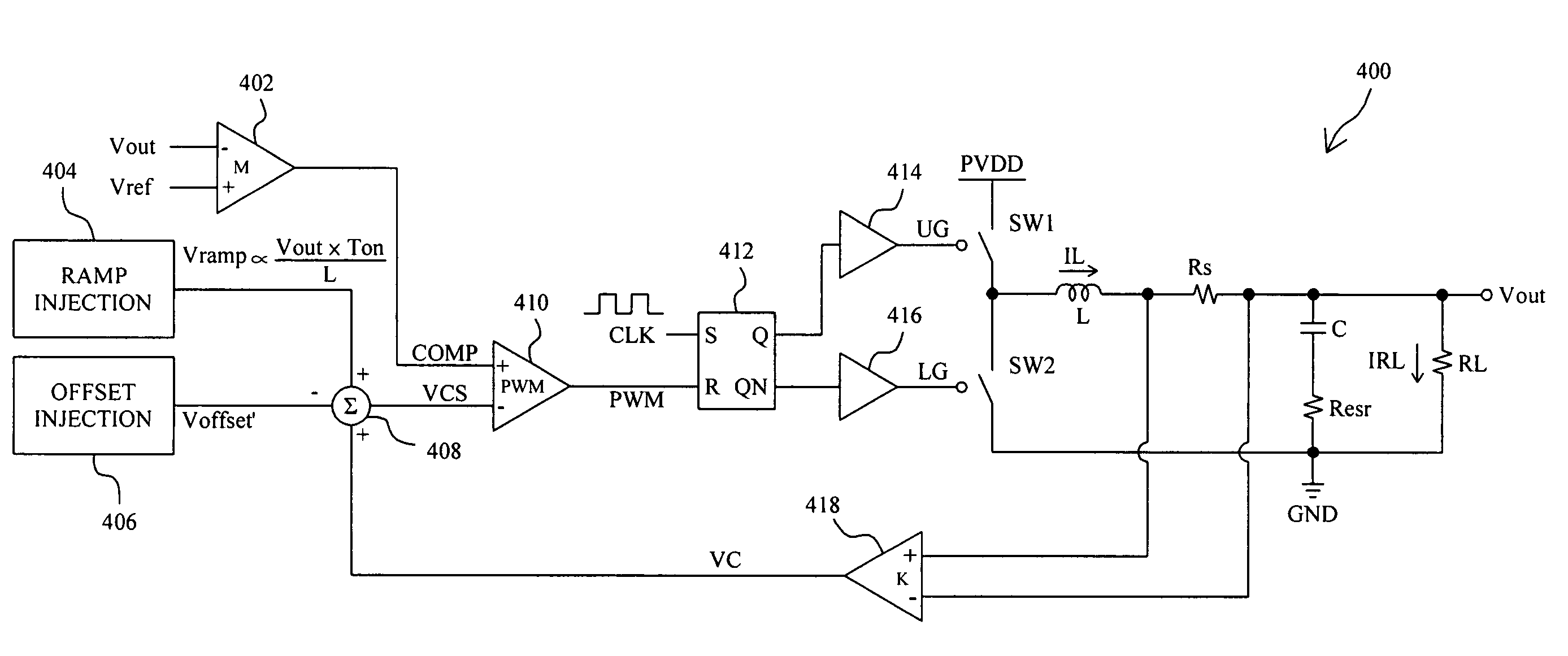
[0034]FIG. 11 shows second embodiment according to the present invention. In voltage regulator 600, PWM comparator 608 compares the error signal COMP produced by error amplifier 606 with reference voltage Vref to generate PWM signal, SR latch 610 produces signals UG and LG in response to fixed-frequency CLK and PWM signal to switch switches SW1 and SW2 with drivers 612 and 614, respectively, to produce inductor current IL flowing through inductor L to charge output capacitor C to thereby generate output voltage Vout, transconductive amplifier 616 serves as current sense circuit to generate current sense signal VC based on the voltage drop across sense resistor Rs coupled in series to the inductor L to couple to positive input of summing circuit 618, ramp injection circuit 602 supplies ramp signal Vramp to another positive input of the summing circuit 618, offset injection circuit 604 supplies offset voltage Voffset′ to negative input of the summing circuit 618, the summing circuit 6...
PUM
 Abstract
Description
Claims
Application Information