Probe receptacle for mounting a probe for testing semiconductor components, probe holder arm and test apparatus

a technology for mounting probes and semiconductor components, applied in the direction of electrical testing, measurement devices, instruments, etc., to achieve the effect of simple design, robust and inexpensive, and simple manner

Inactive Publication Date: 2009-07-14
CASCADE MICROTECH
View PDF6 Cites 2 Cited by
  • Summary
  • Abstract
  • Description
  • Claims
  • Application Information

AI Technical Summary

Benefits of technology

[0007]The socket opening which is designed to receive a prismatic probe shaft and is surrounded by a base wall makes it possible to arrange the probe in the test apparatus in a reproducible manner. At the same time, the at least two base wall segments make it possible to firmly clamp the probe shaft of a probe, which is inserted into the socket opening, in the socket opening using the action of external forces. This makes it possible to produce higher clamping forces which remain the same even at high temperatures, thus achieving reliable contact-connection of the probe needle.
[0009]According to a second refinement of the invention, the base wall is composed of at least two base wall segments which are independent of one another and can be moved toward one another. In other words, the base wall was formed by subsequently joining together individually produced base wall segments. This solution provides for at least that part of the base which forms the socket opening to be formed from a plurality of base wall segments which are independent of one another. As in the first refinement described above, the base wall segments can be rigidly mounted and can be moved toward one another by means of deformation. However, the more complicated design of the base comprising independent base wall segments also makes it possible for said segments to be mounted in a movable manner, in which case spring elements can be provided for the purpose of generating a restoring force which releases the probe shaft situated in the socket opening when no external forces are acting on the base wall segments.
[0010]According to another refinement of the invention, provision is also made of at least one clamping means for generating a clamping force that acts on the base wall segments. Although it is, of course, possible to provide a clamping means independently of the probe receptacle and in addition to the latter when the probe receptacle is used in a test apparatus, or to configure the probe receptacle in such a manner that it does not require an additional clamping means, it is nevertheless advantageous to design the clamping means as part of the probe receptacle. This makes it possible to achieve a particularly compact design.
[0012]One development of the invention provides for the outer surface of the base to have a cylindrical second region and for the inner surface of the clamping sleeve to have a cylindrical second region which can be moved in the axial direction, that is to say in the longitudinal direction of the socket opening, in the second region of the outer surface of the base. The practice of designing the base and the clamping sleeve such that they each have a cylindrical second region assists the axial relative movement of the clamping sleeve on the base and ensures that the clamping sleeve is guided exactly on the surface of the base.
[0016]Provision may advantageously be made for the number of slots to be even. In the simplest case, the base has two slots. The two resulting base wall segments can be clamped in a particularly simple manner if the two slots are arranged such that they are essentially opposite with respect to the socket opening, for example by virtue of the base being surrounded by a clamping collar. This simple solution results in a robust and inexpensive probe receptacle of simple design.
[0017]Provision may also advantageously be made to provide four base wall segments. This design has proven to be particularly advantageous when the prismatic probe shaft has a rectangular cross section. The base can be produced in a particularly simple manner when the slots which are present between the base wall segments are opposite one another in pairs with respect to the socket opening.

Problems solved by technology

However, the more complicated design of the base comprising independent base wall segments also makes it possible for said segments to be mounted in a movable manner, in which case spring elements can be provided for the purpose of generating a restoring force which releases the probe shaft situated in the socket opening when no external forces are acting on the base wall segments.

Method used


Image

  • Probe receptacle for mounting a probe for testing semiconductor components, probe holder arm and test apparatus
  • Probe receptacle for mounting a probe for testing semiconductor components, probe holder arm and test apparatus
  • Probe receptacle for mounting a probe for testing semiconductor components, probe holder arm and test apparatus

Examples


Embodiment Construction

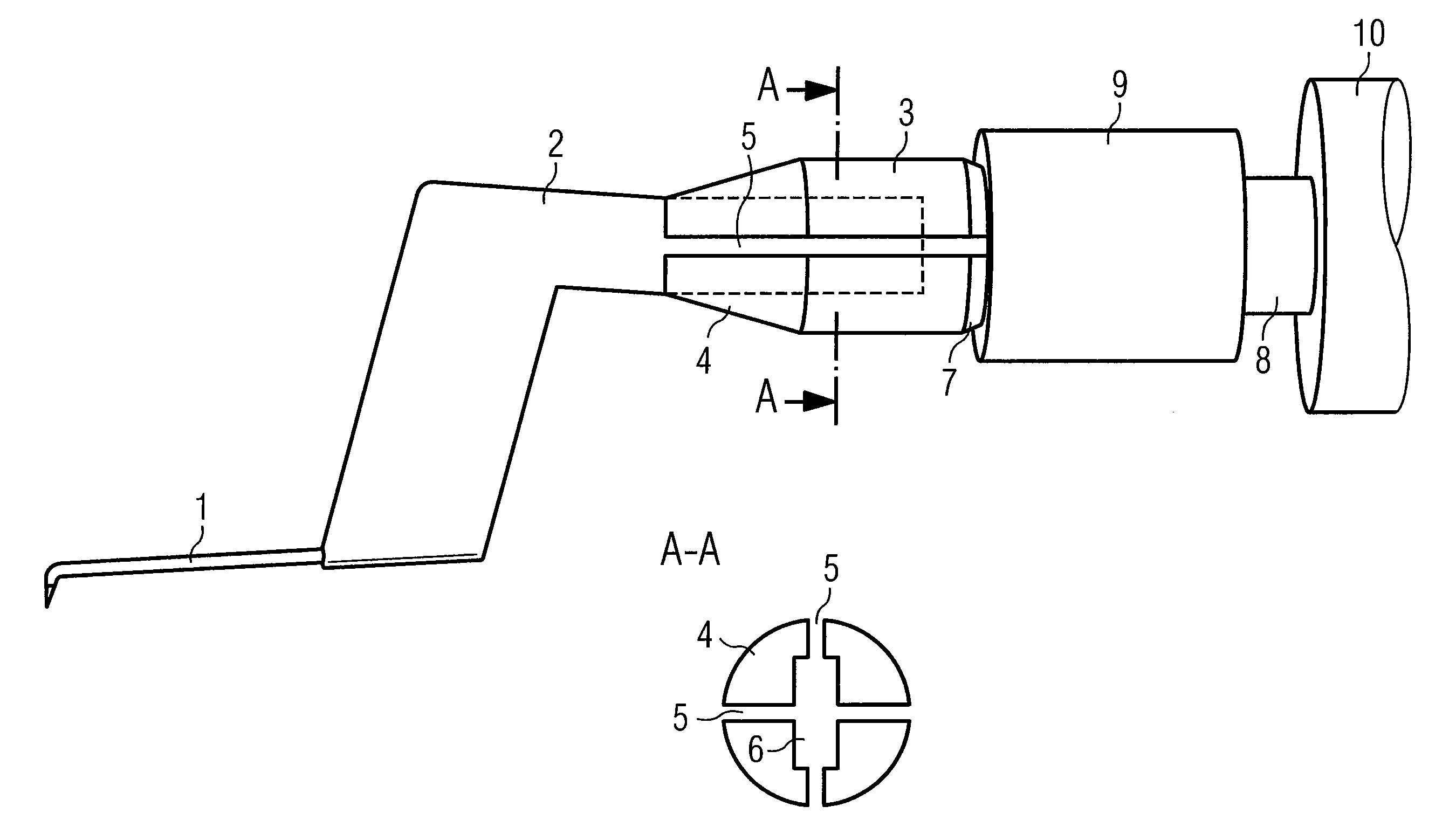
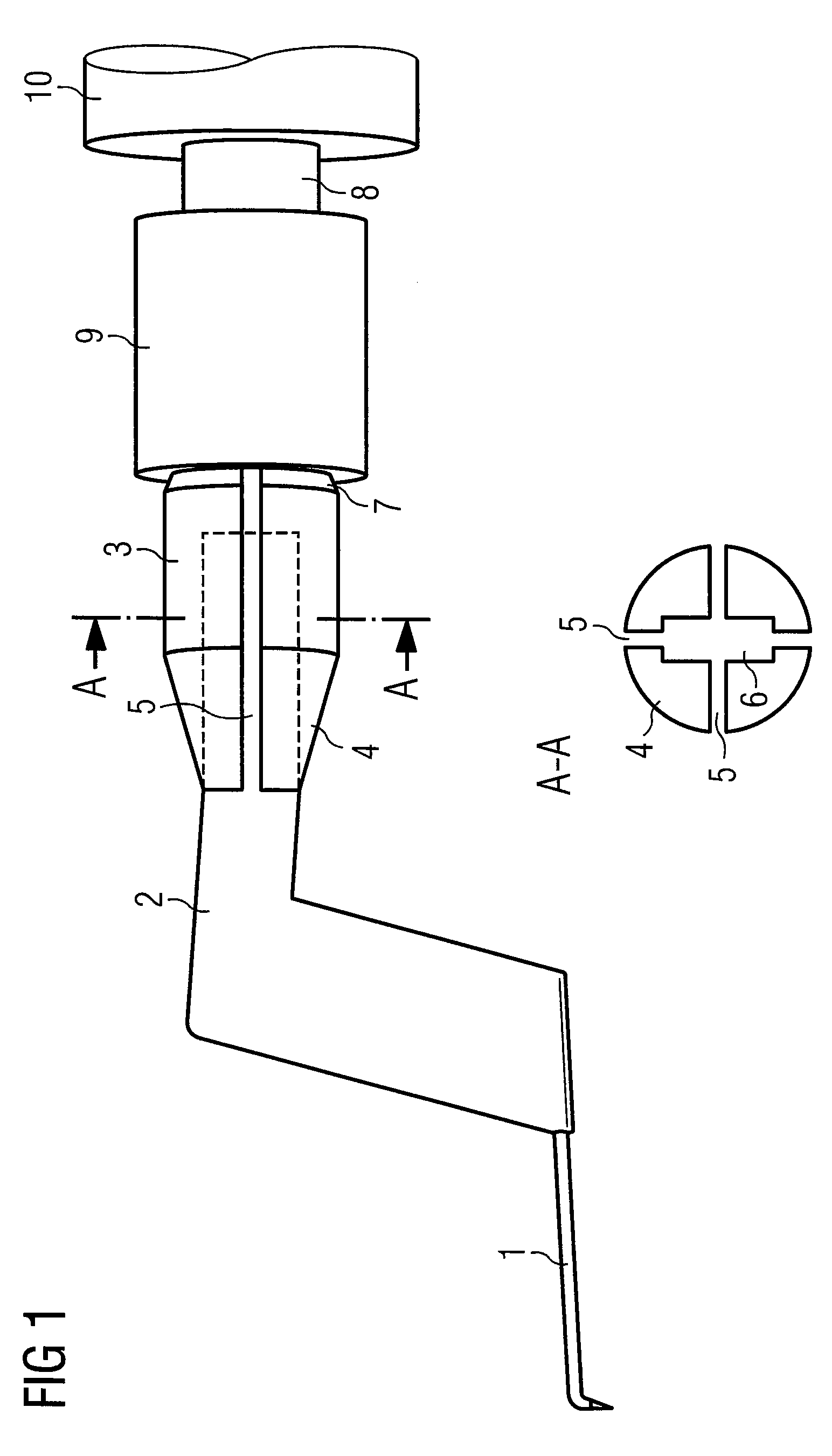
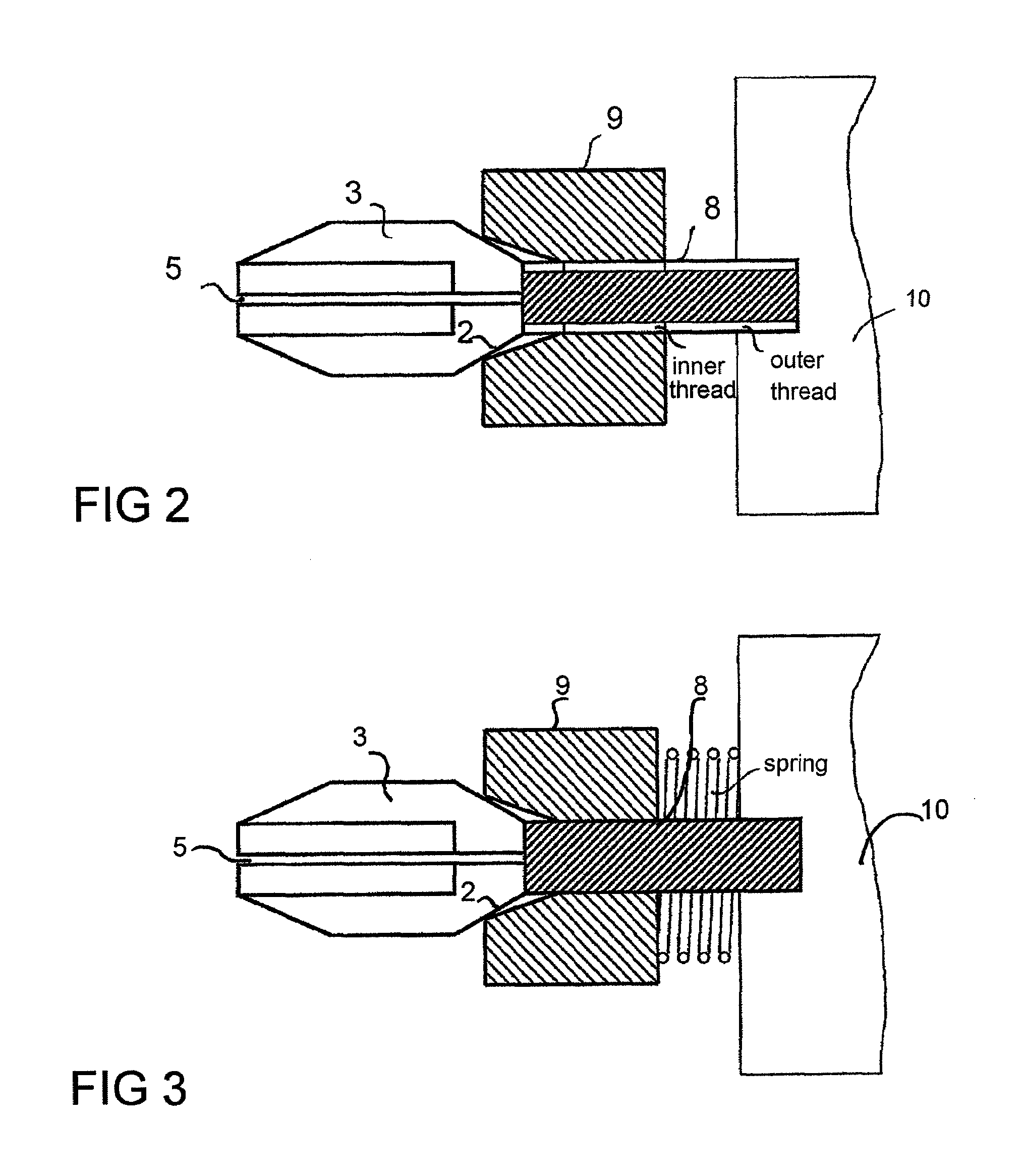
[0023]As illustrated in FIG. 1, the inventive probe receptacle is fastened to the free end of a probe holder arm 10 which is arranged in a test apparatus. The probe receptacle comprises a base 3 and a clamping sleeve 9 which sits on the base 3. In order to receive a prismatic probe shaft 2 having a rectangular cross section, a socket opening 6 which likewise has a rectangular cross section is centrally arranged in the base 3. The base 3 is divided into four base wall segments 4 by means of four slots 5 which are arranged such that they are opposite one another with respect to the socket opening 6. In the exemplary embodiment with the socket opening 6 and the slots 5, the base 3 is produced using spark erosion.

[0024]The prismatic probe shaft 2 is inserted into the socket opening 6. In the exemplary embodiment, this prismatic probe shaft 2 is angled. The probe needle 1 is arranged at the free end of the probe shaft 2 and is firmly connected to the probe shaft 2. The probe is electrica...


PUM


Abstract

To arrange a probe needle in a reproducible manner, ensure reliable contact-connection of the probe needle and ensure that the probe needle is held securely even at high temperatures or test forces, a probe receptacle is provided for mounting a probe for testing semiconductor components. The probe has a probe needle and an essentially prismatic probe shaft. The probe receptacle comprises a base having a socket opening to receive the prismatic probe shaft, surrounded by a base wall. The base wall comprises at least two base wall segments which can be moved toward one another. A probe holder arm having such a probe receptacle, and test apparatus having at least one probe which has such a probe receptacle are also provided.

Description

BACKGROUND ART[0001]The invention relates to a probe receptacle for mounting a probe for testing semiconductor components to a probe holder arm and to a test apparatus.[0002]In order to test the functionality of semiconductor components, the semiconductor components, which are usually still combined with other semiconductor components and are arranged on a wafer at this point in time, are placed and fastened in a test apparatus, which is provided for this purpose, on a movable test table (chuck). The semiconductor component is then contact-connected using a probe so that measurements can be carried out. The probe, which is in the form of a needle and is also referred to as a probe tip, is usually fastened either to a carrier plate (probe card) or to a probe holder arm (probe arm). In many known test apparatuses, the probe holder arm extends from a probe head, to which the probe holder arm is fastened, into the vicinity of the surface of the chuck or of the wafer which is arranged on...

Claims


Application Information

Patent Timeline
Patent Type & Authority Patents(United States)
IPC IPC(8): G01R1/067
CPCG01R31/2891G01R31/2874
Inventor FLEISCHER, HANS-JURGENSCHMIDT, AXELKANEV, STOJANBECKER, AXEL
Owner CASCADE MICROTECH
Why Eureka
Try Eureka