LED projector headlamps using single or multi-faceted lenses

a technology of led projectors and headlamps, applied in the field of headlamps, can solve problems such as limited control, and achieve the effect of improving light collection

Inactive Publication Date: 2009-07-21
VARROC LIGHTING SYST SRO
View PDF33 Cites 28 Cited by
  • Summary
  • Abstract
  • Description
  • Claims
  • Application Information

AI Technical Summary

Benefits of technology

[0006]The present invention provides a condenser lens and a headlamp assembly employing the condenser lens which improves control over the beam spread characteristics, while at the same time reduces the package size of the headlamp assembly. According to one embodiment, a condenser lens is provided for a projector-type headlamp assembly having a light source emitting light which is projected longitudinally downstream in front of a motor vehicle. The condenser lens generally includes a main body of light transmitting material. The main body defines a first surface receiving light from the light source and a second surface emitting the light. The second surface has at least one facet structured to spread the light and provide a predetermined beam pattern.
[0008]Another embodiment constructed in accordance with the teachings of the present invention provides a projector-type headlamp assembly for a motor vehicle which generally includes a light source, a reflector, and a condenser lens. The condenser lens is constructed in a fashion similar to the numerous constructions described above, thereby providing a predetermined beam pattern. By shifting the duties of spreading the light to the condenser lens, the reflector may comprise a simple elliptical reflector having a circular cross-sectional shape. That is, the reflector need not be elongated in the horizontal direction or otherwise specifically constructed to generate the desired beam spread pattern. A shield may also be employed in the projector-type headlamp assembly to provide a horizontal cut-off. Preferably, the shield is tilted slightly away from the light source and toward the lens thereby improving light collection.

Problems solved by technology

In a direct projector unit, no reflector is employed and a limited amount of control, is available over the beam spread through selection of the light source and its position relative to the condenser lens.

Method used


Image

  • LED projector headlamps using single or multi-faceted lenses
  • LED projector headlamps using single or multi-faceted lenses
  • LED projector headlamps using single or multi-faceted lenses

Examples


Embodiment Construction

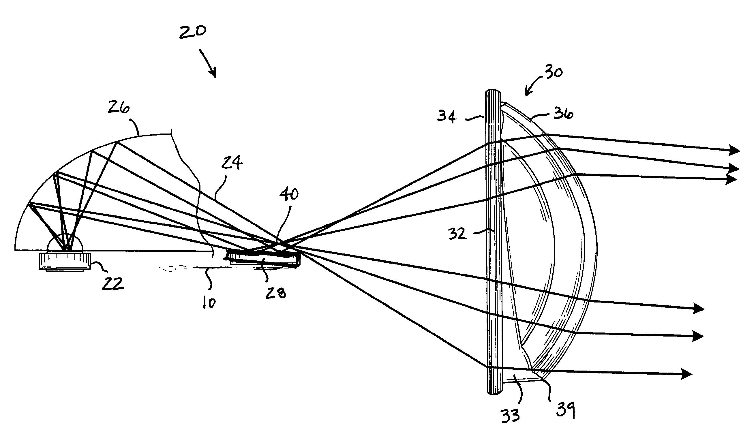
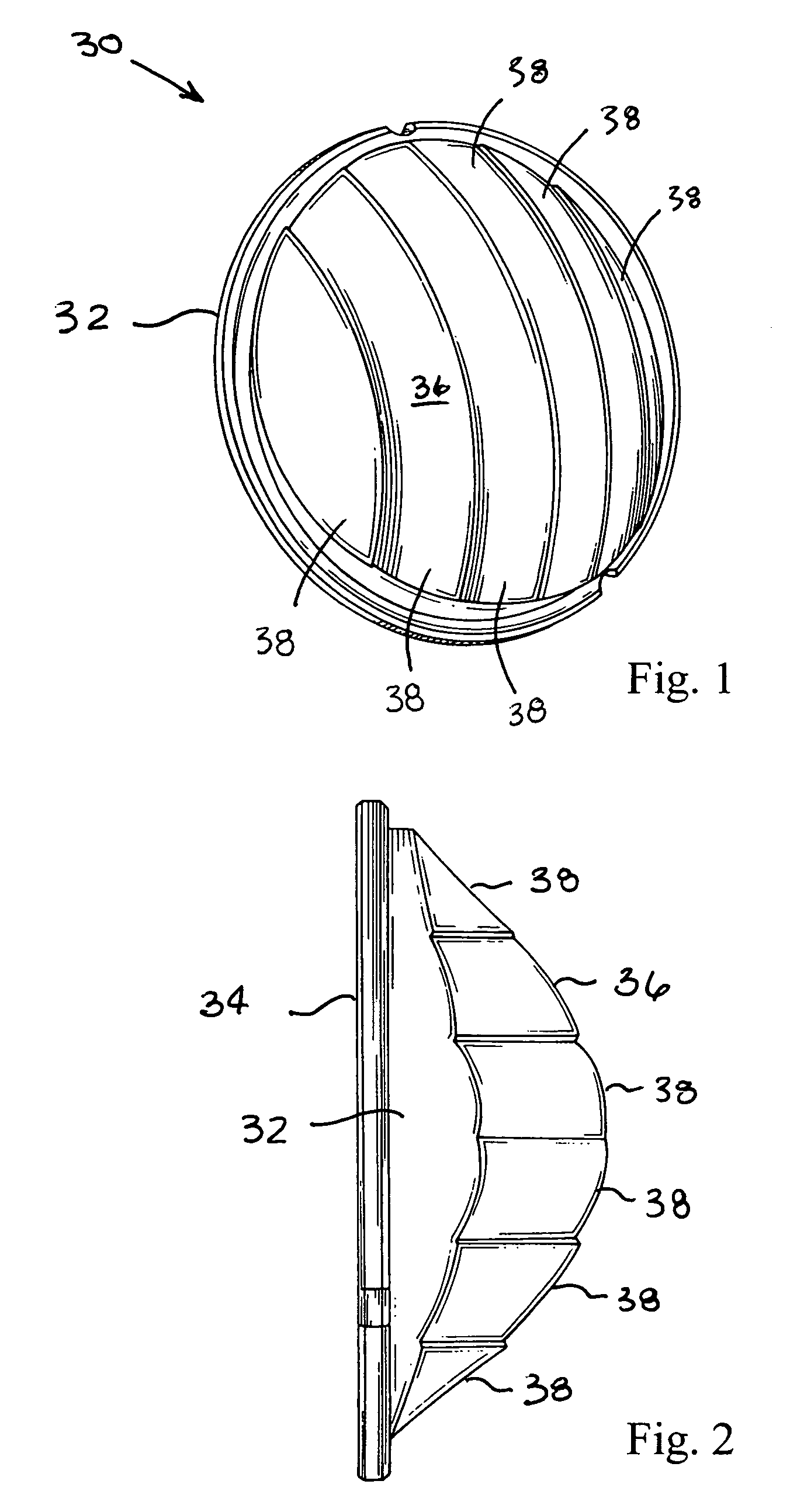
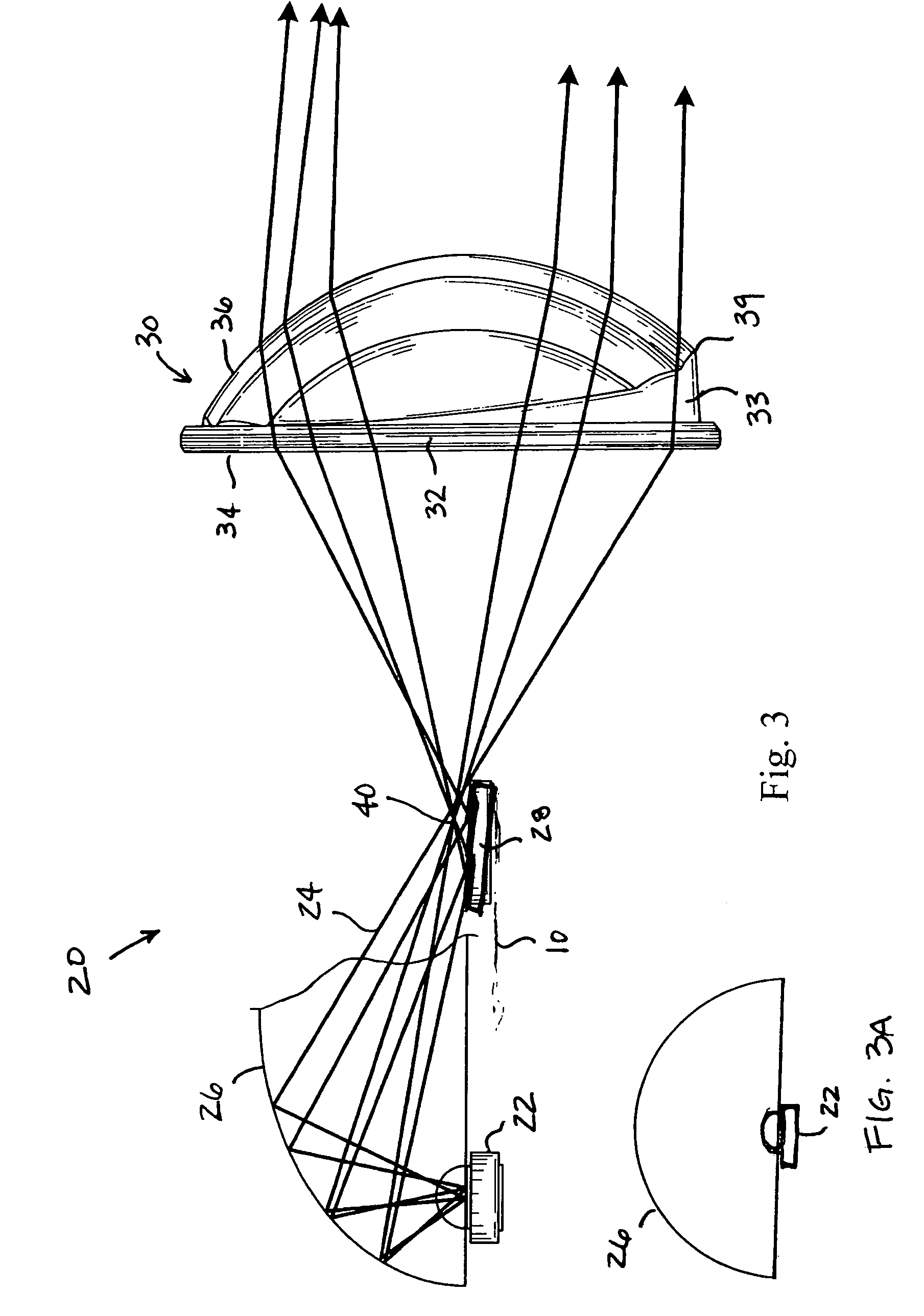
[0023]Turning now to the figures, FIGS. 1 and 2 depict a condenser lens 30 constructed in accordance with the teachings of the present invention. Notably, the condenser lens 30 is capable of imparting beam spread characteristics into the light outputted from the headlamp assembly 20 (FIG. 3) of which it is a part of, as will be discussed in more detail herein below. Additionally, the condenser lens 30 is capable of creating specified vertical spread and horizontal spread functions for each facet, thereby providing a highly adaptable condenser lens which can be tailored for a specific number of vehicles or desired beam characteristics. By moving the function of beam spread from the reflector to the condenser lens, standard elliptical reflectors may be employed in conjunction with LED light sources to provide a light output that is suitable for automotive headlight applications while also having the desired beam characteristics.

[0024]The condenser lens 30 generally comprises a main bo...


PUM


Abstract

A condenser lens and a headlamp assembly employing the condenser lens improves control over the beam spread characteristics, while at the same time reduces the package size of the headlamp assembly. The condenser lens is provided for a projector-type headlamp assembly having a light source emitting light which is projected longitudinally downstream in front of a motor vehicle. The condenser lens generally includes a main body of light transmitting material. The main body defines a first surface receiving light from the light source and a second surface emitting the light. The second surface has at least one facet structured to spread the light and provide a predetermined beam pattern.

Description

FIELD OF THE INVENTION[0001]The present invention relates generally to motor vehicle headlamps, and more particularly relates to headlamps of the projector-type which employ a condenser lens.BACKGROUND OF THE INVENTION[0002]Light emitting diodes (LED's) are fast becoming the preferable light source for automotive lighting applications, as they consume less power but provide light output which is becoming acceptable for such applications. When LED's are employed in headlamps (i.e., headlights), several requirements must be met. Specifically, the beam pattern provided in road illumination should have a certain amount of vertical spread as well as a certain amount of horizontal spread. At the same time, a vertical cut-off should be provided to minimize glare to oncoming traffic.[0003]Generally, headlamps for motor vehicles can be characterized as reflector-type headlamps or projector-type headlamps. Reflector-type headlamps employ a specially structured reflector unit which collects an...

Claims


Application Information

Patent Timeline
Patent Type & Authority Patents(United States)
IPC IPC(8): F21V5/00H01L33/00H01L33/58
CPCF21S48/1159F21S48/1163F21S48/1258F21S48/1388F21S48/145F21S48/1283F21Y2101/02F21Y2115/10F21S41/255F21S41/26F21S41/265F21S41/321F21S41/43F21S41/365F21S41/148B60Q1/04F21V7/0033F21W2102/00F21Y2101/00
Inventor CHINNIAH, JEYACHANDRABOSEFALLAHI, AMIR P.SAYERS, EDWIN M.
Owner VARROC LIGHTING SYST SRO
Why Eureka
Try Eureka