Method and apparatus for extending the life of matrix addressed emissive display devices

Active Publication Date: 2009-07-21
ROCKWELL COLLINS INC
View PDF11 Cites 1 Cited by
  • Summary
  • Abstract
  • Description
  • Claims
  • Application Information

AI Technical Summary

Benefits of technology

[0005]A method of reducing luminance decay of emissive elements in a matrix addressed emissive display device includes generating control data corresponding to a static image to be displayed on a matrix of individually addressable emissive display elements. Drive signals are generated as a function of the control data, and are provided to the matrix to thereby energize the corresponding emissive display elements of the matrix in order to display the static image on the matrix. The control data are altered substantially continuously in order to substantially continuously move the static image on the matrix.

Problems solved by technology

In particular, matrix emissive display devices which are used to continuously or frequently display static images will experience decay of the emissive elements more rapidly.
While techniques such as line translation have been used to slow the decay of emissive elements in cathode ray tube (CRT) display devices which display static images such as vertical or horizontal lines, techniques for slowing or preventing the decay of emissive elements in matrix addressed emissive display devices have been generally unavailable.

Method used


Image

  • Method and apparatus for extending the life of matrix addressed emissive display devices
  • Method and apparatus for extending the life of matrix addressed emissive display devices
  • Method and apparatus for extending the life of matrix addressed emissive display devices

Examples


Embodiment Construction

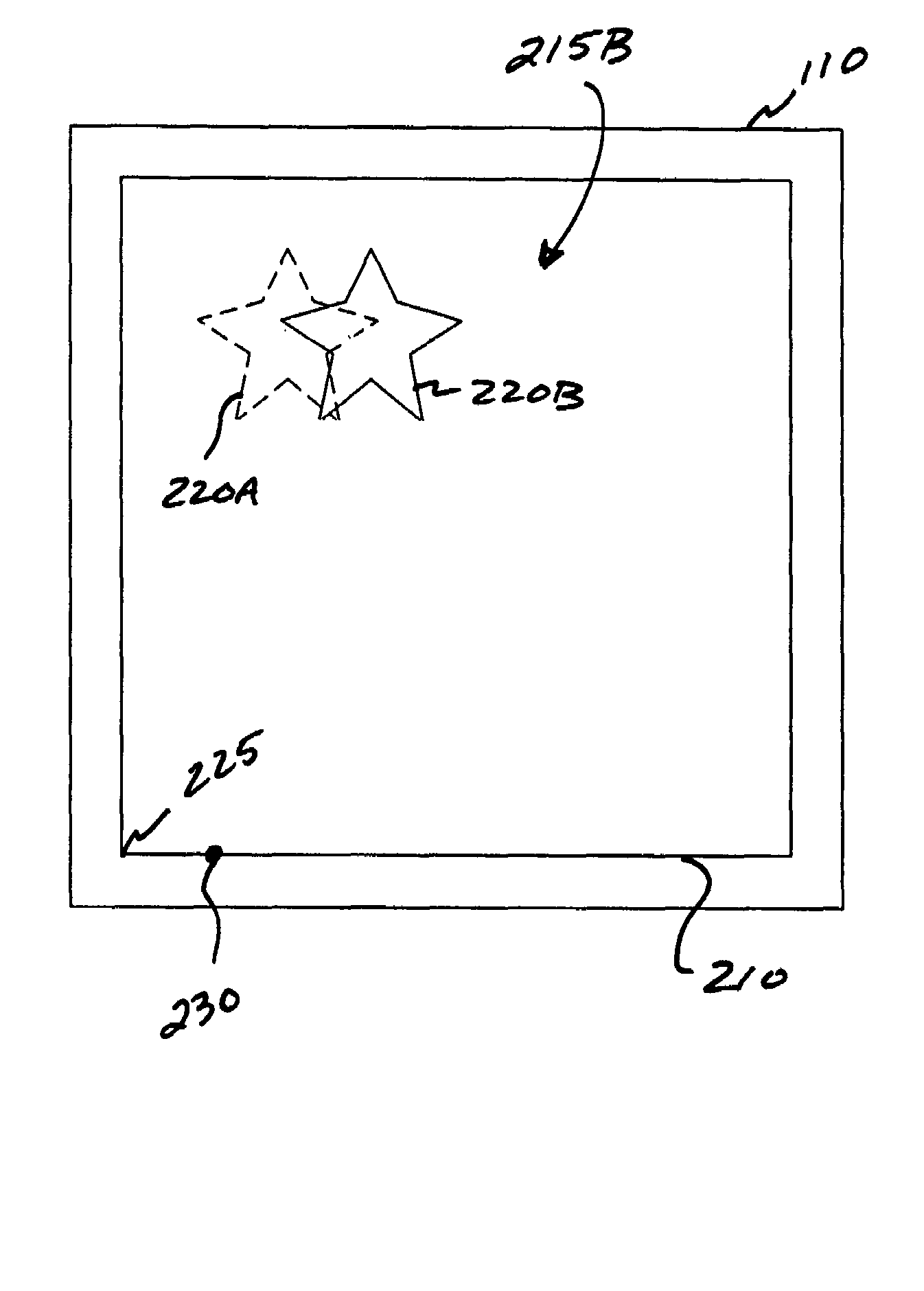
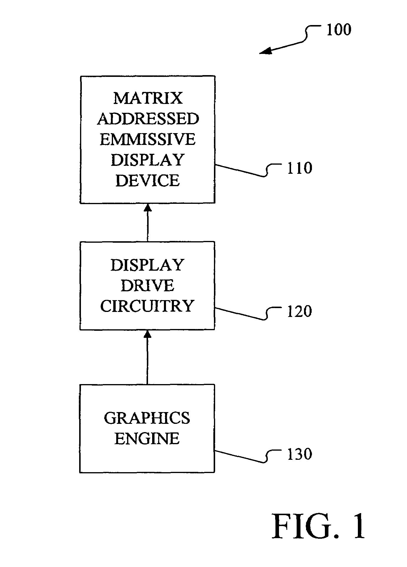
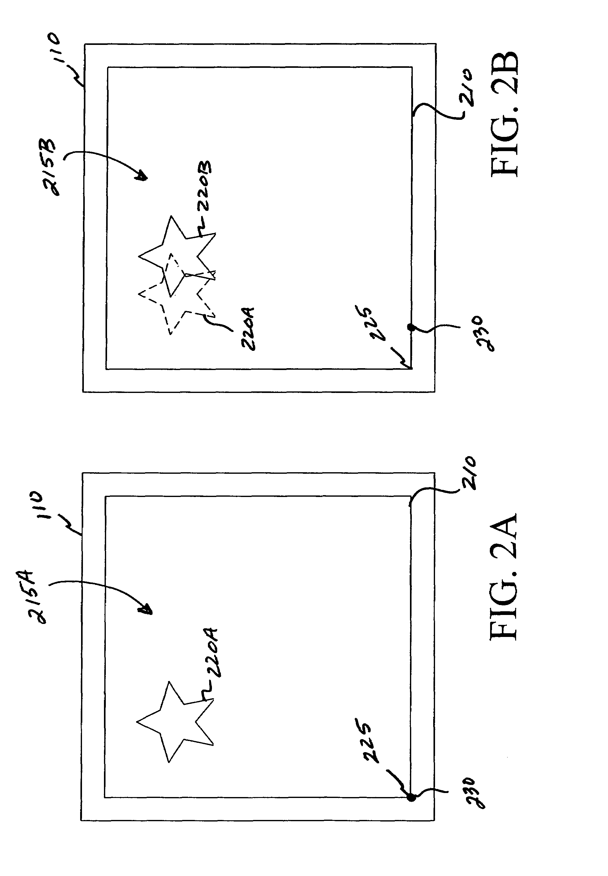
[0009]FIG. 1 is a block diagram illustrating display system 100 in accordance with embodiments of the present invention. Display system 100 includes a matrix addressed emissive display device 110, display drive circuitry 120 and a graphics engine 130. Matrix emissive display device 110 is a FED, a plasma display, an LED display, or other types of emissive display devices which utilize a matrix of individually controllable emissive display elements or pixels. Display drive circuitry 120 includes circuitry of the type known in the art which is used to individually energize the emissive display elements in matrix emissive display device 110 in order to display an image on the matrix of emissive elements.

[0010]Graphics engine 130 is a microprocessor or microprocessor based system adapted to generate the data required to control display drive circuitry 120 to display a particular image on matrix emissive display device 110. Thus, graphics engine 130 ultimately controls the operation of d...


PUM


Abstract

A method of reducing luminance decay of emissive elements in a matrix addressed emissive display device includes generating control data corresponding to a static image to be displayed on a matrix of individually addressable emissive display elements. Drive signals are generated as a function of the control data, and are provided to the matrix to thereby energize the corresponding emissive display elements of the matrix in order to display the static image on the matrix. The control data are altered substantially continuously in order to substantially continuously move the static image on the matrix.

Description

FIELD OF THE INVENTION[0001]The present invention relates to matrix addressed emissive display devices. More particularly, the present invention relates to methods and apparatus which can be used to reduce luminance decay of emissive elements in matrix addressed emissive display devices.BACKGROUND OF THE INVENTION[0002]Matrix addressed emissive display devices utilize a matrix or array of emissive display elements or pixels which are individually controllable to display an image. Matrix addressed emissive display devices include, for example, light emitting diode (LED) displays, field effect displays (FEDs), and plasma displays. A common type of matrix addressed emissive display device is an LED display device utilizing organic light emitting diodes.[0003]Decay of the emissive elements of emissive display devices occurs with usage. In particular, matrix emissive display devices which are used to continuously or frequently display static images will experience decay of the emissive e...

Claims


Application Information

Patent Timeline
IPC IPC(8): G09G3/22G06F3/048H04N3/20
CPCG09G3/007G09G3/22G09G2320/046
Inventor STEFFENSMEIER, MARTIN J.NAEVE, RANDY A.ROHR, THOMAS C.WOELK, LINLEY E.
Owner ROCKWELL COLLINS INC
Why Eureka
Try Eureka