Catadioptric imaging system for high numerical aperture imaging with deep ultraviolet light

a technology of catadioptric imaging and ultraviolet light, applied in the field of imaging systems, can solve problems such as limited beaming, and achieve the effects of reducing te polarization components, and reducing tm polarization components of rays

Inactive Publication Date: 2009-07-21
CORNING INC
View PDF14 Cites 10 Cited by
  • Summary
  • Abstract
  • Description
  • Claims
  • Application Information

AI Technical Summary

Benefits of technology

[0011]The field-correcting lens preferably includes a lens body having first and second sides located along the optical axis. The convex refractive surface is at a first side of the lens body and another refractive surface is at a second side of the lens body. The refractive surface at the second side of the lens body preferably forms an immersion interface shaped for refracting the light into a liquid optical medium adjacent to the image plane. Overall, the field-correcting lens can have a net positive power, and the immersion interface can have a nominally planar form. Alternatively, the immersion interface can have a concave form for reducing refraction between the field-correcting lens and the liquid medium.
[0034]The angularly sensitive polarizer preferably polarizes the overlapping bundles of rays within the pupil with a radial symmetry that reduces TM polarization components of the rays parallel to axial planes of incidence at the image plane without substantially reducing TE polarization components of the rays perpendicular to the axial planes of incidence at the image plane. The TM polarization components of the rays are subject to variation in inclination to the reference axis complementary to the inclination of the rays to the reference axis at the image plane. The TE polarization components of the rays remain orthogonal to the reference axis despite the inclination of the rays to the reference axis at the image plane. As such, the polarizer preferably reduces the TM polarization components of the rays as a function of the inclination of the rays to the reference axis at the image plane.

Problems solved by technology

Aberrations are limited by design improvements that exploit the focusing power of reflective optics together with the corrective properties of refractive optics at low refraction angles.

Method used


Image

  • Catadioptric imaging system for high numerical aperture imaging with deep ultraviolet light
  • Catadioptric imaging system for high numerical aperture imaging with deep ultraviolet light
  • Catadioptric imaging system for high numerical aperture imaging with deep ultraviolet light

Examples


Embodiment Construction

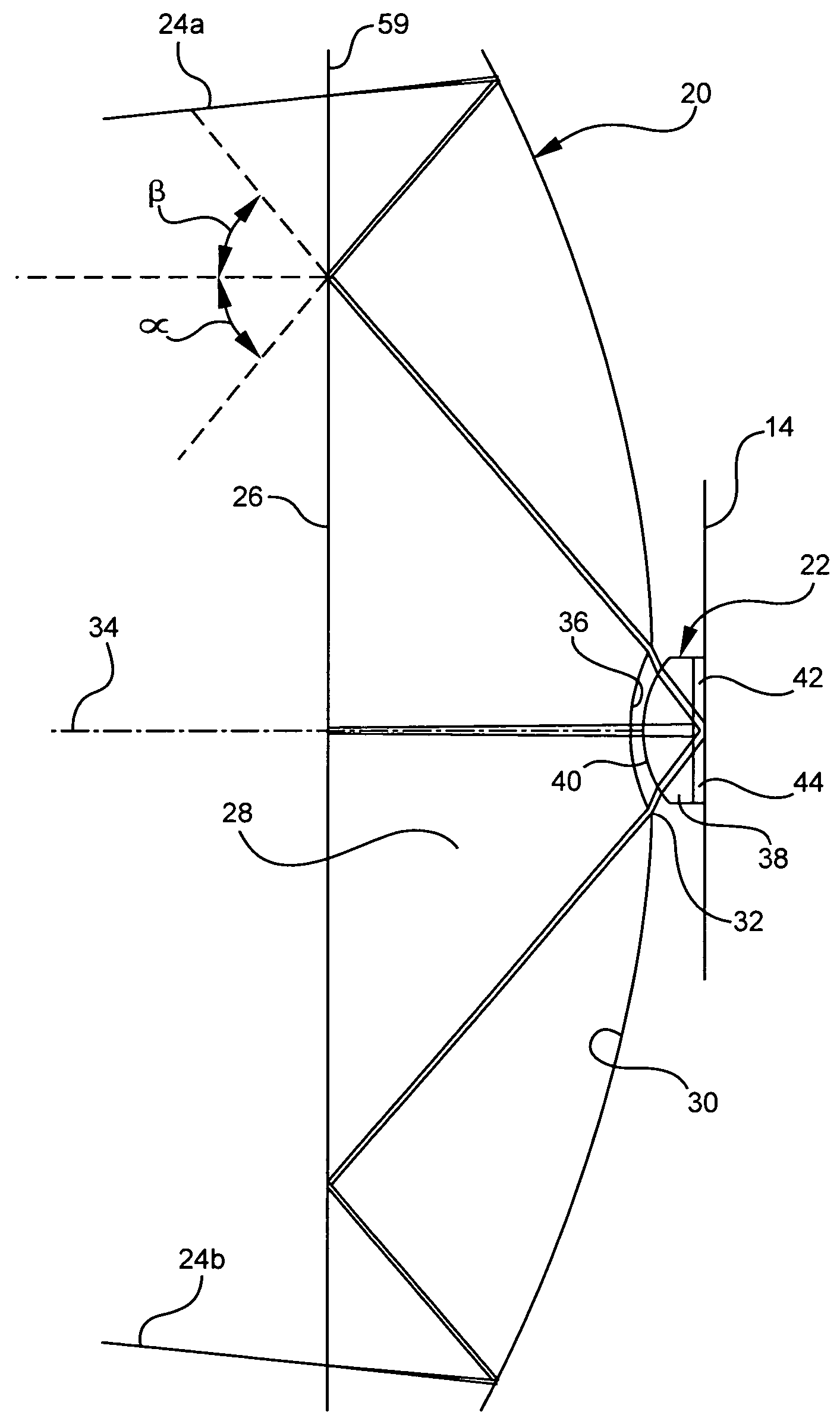
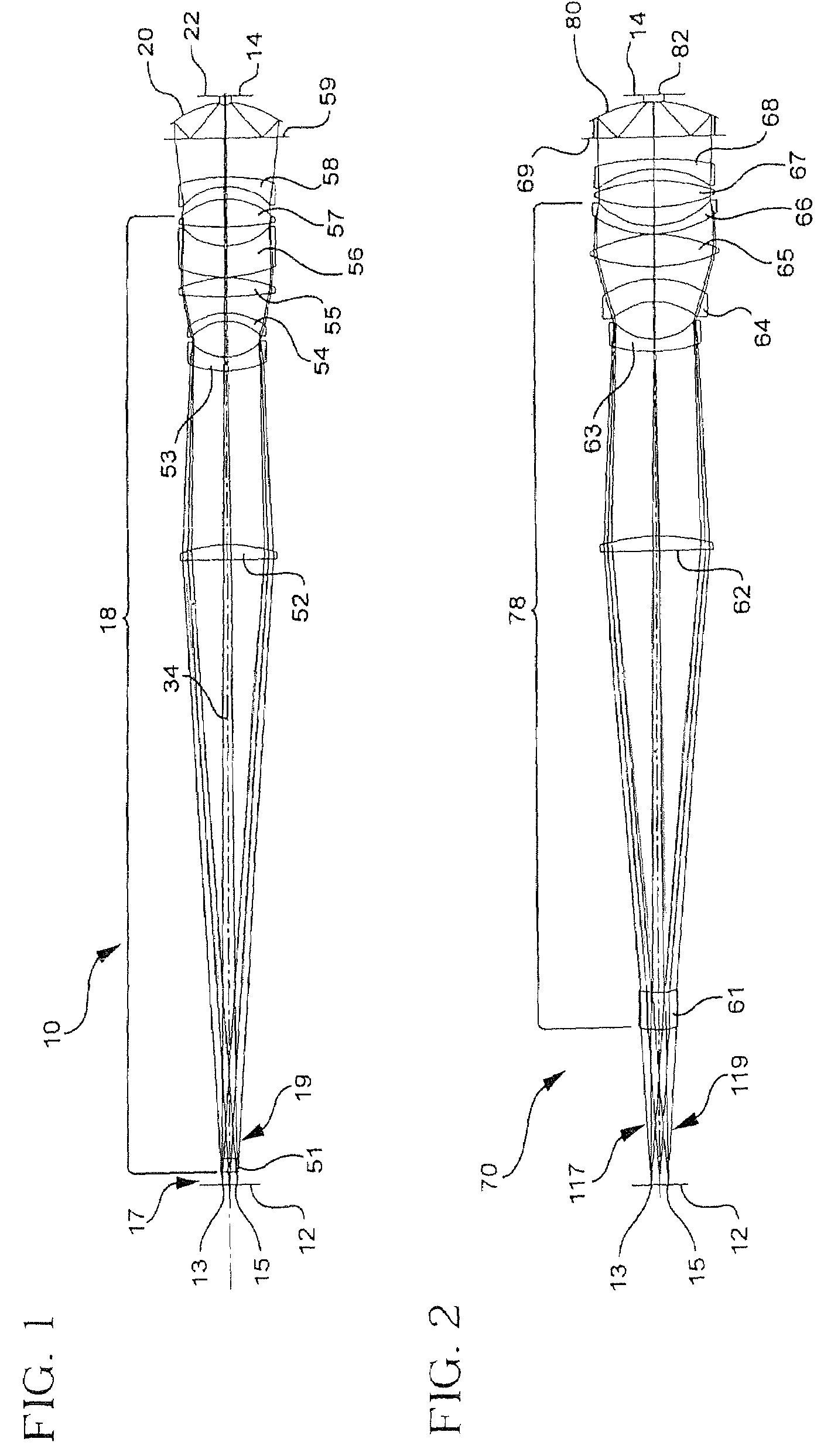
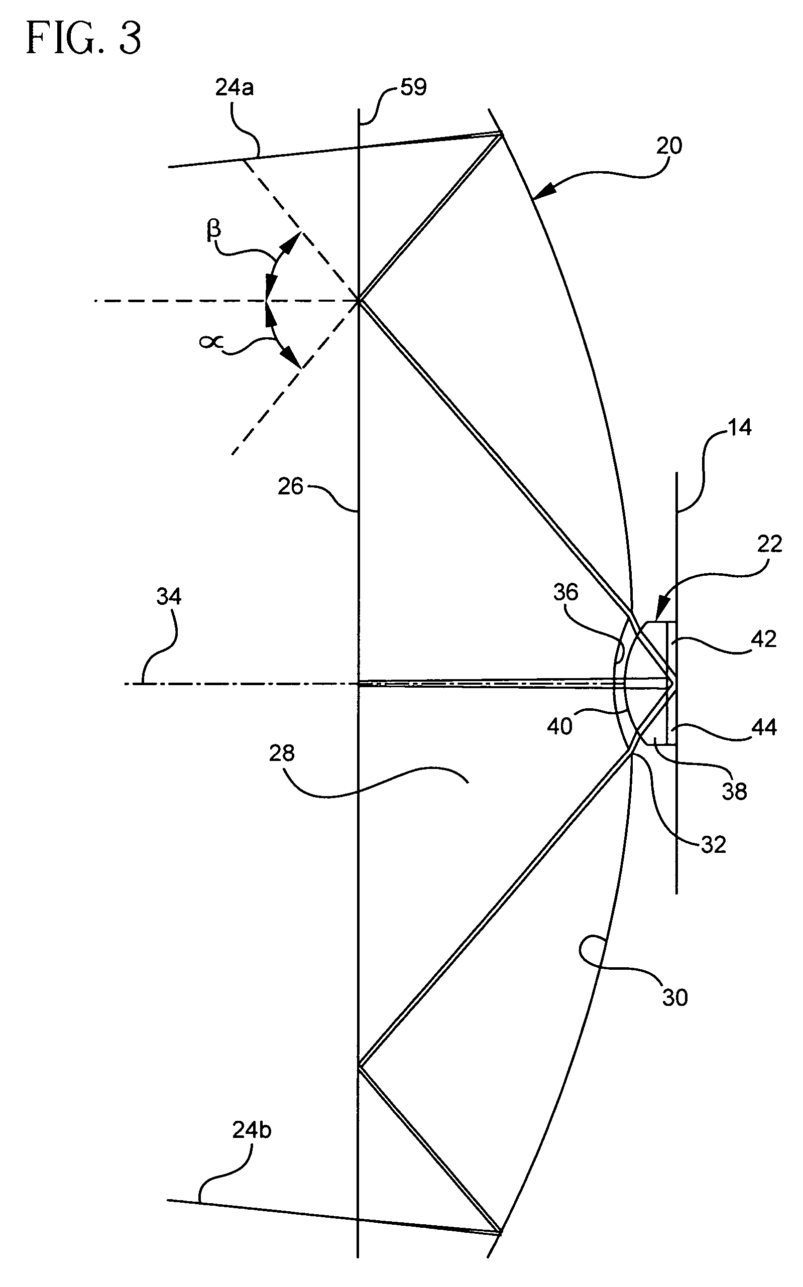
[0042]A catadioptric imaging system 10 for microlithographic projection is shown in FIG. 1 in an arrangement for imaging a reticle 12 (object) onto a resist 14 (image). An enlarged view of a double-reflecting Mangin mirror 20, which provides substantial focusing power for the imaging system 10, is shown in FIG. 3. An assembly 18 of largely refractive components is arranged for filling the aperture of the double-reflecting Mangin mirror 20 while assisting in the correction of aberrations. Throughout the assembly 18, refraction angles are minimized to avoid the introduction of unnecessary aberrations. A field correcting optic 22 operating in an immersion mode works in conjunction with the Mangin mirror 20 to produce a final image of the reticle 12 on a focal plane of the resist 14.

[0043]The focusing power of the double-reflecting Mangin mirror 20, which is positioned at or near a pupil of the imaging system 10, is apparent from the depicted paths of marginal rays 24a and 24b through t...


PUM

PropertyMeasurementUnit
wavelengthsaaaaaaaaaa
refraction anglesaaaaaaaaaa
angles of incidenceaaaaaaaaaa

Abstract

A catadioptric imaging system for micro-lithographic projection features a high numerical aperture objective where most of the focusing power is produced by reflection and refraction angles are limited to avoid additional aberration. A field correcting optic is appended to a Mangin mirror in an immersive configuration for raising the numerical aperture. The optical connection between the Mangin mirror and the field correcting optic is arranged to control refraction angles by limiting angles of incidence or refractive index differences. A radially symmetric polarizing effect is achieved in a pupil to improve image contrast.

Description

BACKGROUND OF THE INVENTION[0001]1. Field of the Invention[0002]The invention relates to imaging systems of the type in which a reflective surface provides substantial focusing power and more particularly relates to catadioptric reducing systems that exploit a combination of reflection and refraction for focusing purposes. The invention has particular applicability to Newtonian objectives for microlithographic imaging at high numerical apertures using deep ultraviolet light. The invention also contemplates issues of polarization management for imaging systems.[0003]2. Description of Related Art[0004]Newtonian design forms in which focusing power is attained largely by reflection have been incorporated into microlithographic instruments to accurately project images while limiting chromatic aberrations. The chromatic advantages of Newtonian design forms over all-refractive imaging systems are particularly evident for imaging with ultraviolet light where transmissive material choices a...

Claims


Application Information

Patent Timeline
Patent Type & Authority Patents(United States)
IPC IPC(8): G02B17/00G02B27/28G02B7/18G02B17/08G03F7/20
CPCG02B17/0808G03F7/70225G02B17/0892G02B17/086G02B17/02G02B7/18G02B17/00
Inventor WEBB, JAMES EDSON
Owner CORNING INC
Why Eureka
Try Eureka