Method and system for communications with reduced complexity receivers

a receiver and receiver technology, applied in the field of communication systems utilizing reduced complexity receivers, can solve the problems of significant increase in receiver complexity, cost, size and power consumption, proposed techniques suffer from lack of performance in some or all, and achieve low complexity, low cost, and small component size

Inactive Publication Date: 2009-07-21
KOSTIC ZORAN
View PDF15 Cites 17 Cited by
  • Summary
  • Abstract
  • Description
  • Claims
  • Application Information

AI Technical Summary

Problems solved by technology

Modern communications receivers, such as multiple-antenna receivers in wireless systems, are traditionally comprised of multiple analog receive chains, which significantly increase receiver's complexity, cost, size and power consumption.
Previously proposed techniques suffer from lack of performance in some or all of the previous high priority targets.
The existence of more than one analog RF / IF chain increases power consumption, size and cost of transceivers.
For an N-element array, the total number of RF channels required is N. Therefore, the hardware expense and power consumption of such a system is approximately N times those in a single antenna system.
Furthermore, arrays with multiple feed lines and complicated RF circuits introduce more circuit noise and thus are more difficult to integrate into a small area.
These are significant disadvantages of well known smart antenna transceivers.
The method is limited in that, at desirable (low) switching rates, it creates digital signal aliasing (spectrum folding effect).
Therefore, the switch has to run at undesirably high switching rates.
At higher switching rates, large amount of aliased co-channel noise is propagated, significantly reducing operating signal to noise ratio (SNR) of the proposed receiver, thus making it not useful.
The drawback of this approach and its derivatives [Dinger, R., “A planar version of a 4.0 GHz reactively steered adaptive array,” IEEE Transactions on Antennas and Propagation, March 1986, pp.
A major disadvantage of the approach is the existence of multiple delay lines, which replace multiple RF / IF chain, without obvious reduction is complexity, size, cost, and with unclear performance implications.
The SMILE approach suffers from the fact that the rate of the switching is substantially high, even though digital sub-sampling is used.
In particular, the sampling rate is unacceptably high for multi-channel multi-user systems.
This causes excessively high power consumption.
Using this approach, no further reduction of switching rate is achievable, since it would result in unrecoverable loss of information due to signal aliasing.
This set of approaches incurs significant implementation complexity in analog domain, aggravated by high frequencies at which the methods have to operate.
This increases size, cost and power consumption, though potentially reducing the actual number of analog receiver chains.
Although background material on orthogonality is useful for the invention in the present patent, the literature and patents on this topic do not address the issue of complexity reduction in receivers with multiple antennas and multiple analog receive chains.
Methods described in prior art suffer from one or more of the following inadequacies: a) They run at unaffordably high switching rates—with high power consumption; b) Signal-to-noise ratio is significantly degraded; c) Signal phase and magnitude information is lost; d) Multiple analog chains are replaced by other costly and complex components; e) Received signals experience unrecoverable aliasing; f) None of the known methods addresses or takes advantage of multi-user multi-channel wireless systems' peculiarities.

Method used


Image

  • Method and system for communications with reduced complexity receivers
  • Method and system for communications with reduced complexity receivers
  • Method and system for communications with reduced complexity receivers

Examples


Embodiment Construction

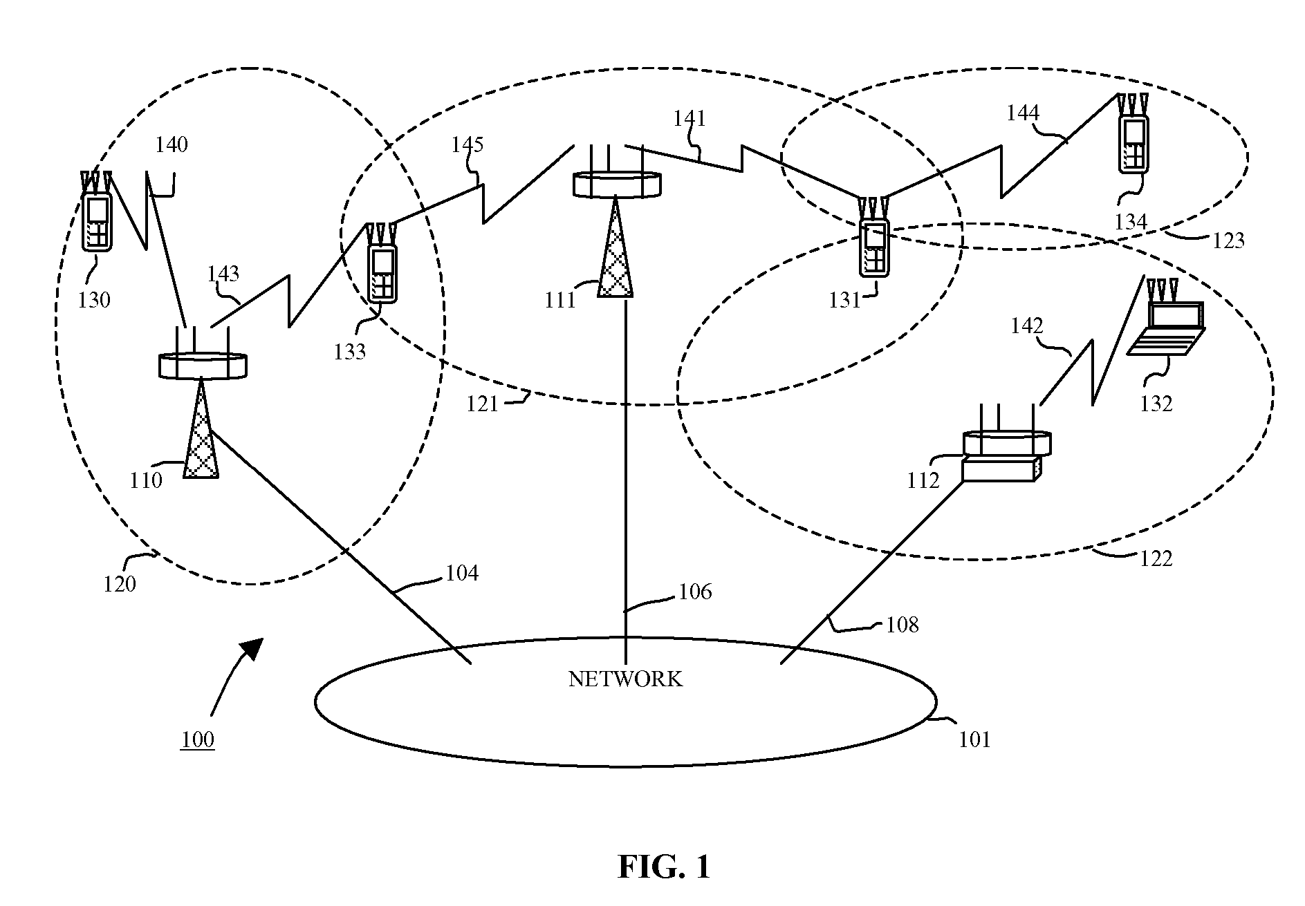
Technical Background—Implementation of Multiple Antenna Transceivers

[0046]Radio transceivers operate at high frequencies and therefore, today, they are built from two separate stages: a) RF / IF-analog stage, and b) Baseband digital stage. Recent transceiver architectures are moving the boundary between the two stages closer to the antenna by reducing the span / size of the analog stage, and by increasing the span / size of the digital stage. Digital processing of signals offers flexibility and precision, but its deployment in radio receivers operating at hundreds of Megahertz is not fully justified today because of high power consumption and cost.

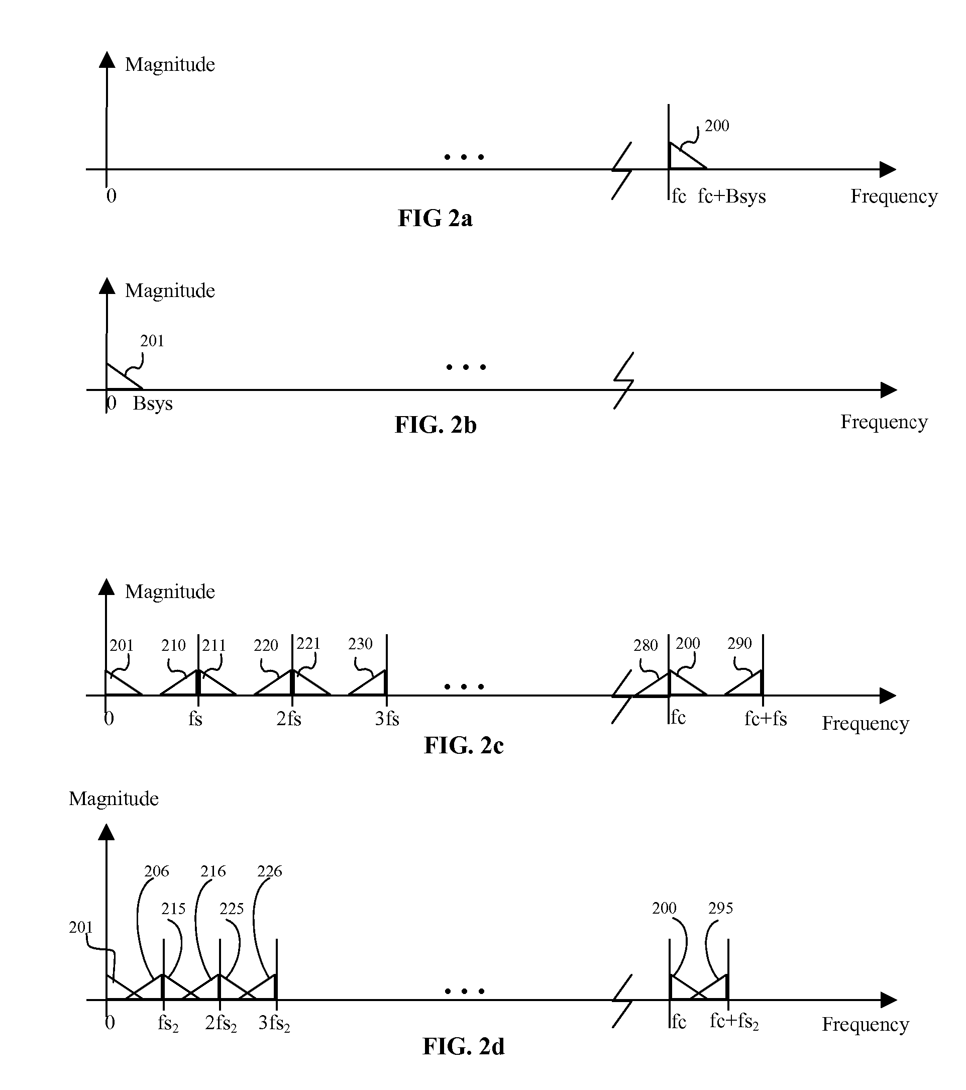
Technical Background—Sub-Sampling (Under-Sampling) Receivers

[0047]Sub-sampling radio architecture supports migration from analog RF / IF components into the digital signal processing (DSP) domain. The reason for migration is the difficulty of analog component design, and variability in analog components which causes signal imbalances. From the per...


PUM


Abstract

The invention provides a new method and system for low complexity, low cost, small component size, and low power communications. The system provides a digital sub-sampling receiver for multiple-antenna wireless receivers, with reduced number of analog RF / IF chains (or one chain) after a fixed number of receive antennas. The system provides a generator of transmit signals / sequences which are preconditioned by the operation of the system to compensate for spectral effects of ultra-low-rate sub-sampling, in that sequences preserve orthogonality under spectral repetition, spectral translation and spectral inversion. The system provides a management device to provide adaptation in transmit signals / waveforms / patterns as a function of channel and data source variations, such that communication data rates and capacities are maximized. The system can efficiently operate in multi-user multi-channel communication systems. The method implemented by the invention is split in its operation across the transmitter of the transmitting device and the receiver of the receiving device.

Description

CROSS-REFERENCE TO RELATED APPLICATIONS[0001]Not applicable.STATEMENT REGARDING FEDERALLY SPONSORED RESEARCH[0002]Not applicable.BACKGROUND[0003]1. Background—Field of the Invention[0004]The present invention relates to communications systems utilizing reduced complexity receivers. The invention relates to systems where receivers typically have more than one receiving chain, such as in multiple-antenna wireless communications. The invention relates to a method and system for designing and combining transmit signals, in combination with receiving signals using digital signal sub-sampling, and using reduced number of analog receiver chains.[0005]2. Background: Statement of the Problem[0006]Reduction of complexity, cost, size and power consumption of communications systems and communication devices is a set of high priority targets for designers of communications systems. Modern communications receivers, such as multiple-antenna receivers in wireless systems, are traditionally comprise...

Claims


Application Information

Patent Timeline
Patent Type & Authority Patents(United States)
IPC IPC(8): H04K1/10
CPCH04B7/0802H04B7/0413Y02D30/70
Inventor KOSTIC, ZORAN
Owner KOSTIC ZORAN
Why Eureka
Try Eureka