Multileaf collimator

a collimator and multi-leaf technology, applied in the field of multi-leaf collimators, can solve the problem that the spacing between the first and second leaf block groups cannot be set to a target configuration accurately

Inactive Publication Date: 2009-07-21
KK TOSHIBA
View PDF2 Cites 35 Cited by
  • Summary
  • Abstract
  • Description
  • Claims
  • Application Information

AI Technical Summary

Benefits of technology

[0007]Therefore, an advantage of the present invention is to provide a multileaf collimator in which the spacing between the first and second leaf block groups can be set to a target configuration accurately.
[0008]To achieve the advantage, one aspect of the present invention provides a multileaf collimator comprising a first leaf block group including a plurality of leaf blocks arranged in a direction, a second leaf block group including a plurality of leaf blocks arranged in the same direction as the first leaf block group, the leaf blocks of the second leaf block group being opposed to the leaf blocks of the first leaf block group in a direction orthogonal to the direction in which the leaf blocks of the first leaf block group are arranged, a plurality of drive mechanisms provided on the respective leaf blocks of the first and second leaf block groups, the drive mechanisms moving the leaf blocks of the first or second leaf block group in an oncoming direction in which the leaf blocks of the first or second leaf block group come close to the leaf blocks of the second or first leaf block or in a departing direction in which the leaf blocks of the first or second leaf block group depart from the leaf blocks of the second or first leaf block group, a plurality of magnetic layers which are provided on the respective leaf blocks of the first and second leaf block groups so as to be positioned on faces of the leaf blocks along a moving direction of the leaf blocks, each of the magnetic layers having a first magnetized part which is magnetized in a north pole and a second magnetized part which is magnetized in a south pole, a plurality of magnetic sensors which are provided on the respective leaf blocks of the first and second leaf block groups, the magnetic sensors being stationary in a noncontact state with respect to the respective leaf blocks, the magnetic sensors varying output signals when the respective leaf blocks are moved in the oncoming direction or the departing direction, and a control device which controls the drive mechanisms according to the output signals delivered by the respective magnetic sensors so that a space defined between the leaf blocks of the first and second leaf blocks is adjusted into a target configuration.
[0009]In the above-described construction, the magnetic layers are provided on the respective leaf blocks of the first and second leaf block groups so as to be positioned on the faces of the leaf blocks along a moving direction of the leaf blocks. Each magnetic layer has the first magnetized part which is magnetized in the north pole and the second magnetized part which is magnetized in the south pole. The magnetic sensors are disposed so as to be stationary in the noncontact state with respect to the magnetic layers. The drive mechanisms are controlled based on the output signals of the magnetic sensors. Consequently, the spacing between the first and second leaf block groups can be set to a target configuration accurately without being adversely affected by variations in the resistance values.

Problems solved by technology

Accordingly, since current positions of the plural leaf blocks cannot be detected accurately, the spacing between the first and second leaf block groups cannot be set to a target configuration accurately.

Method used


Image

  • Multileaf collimator
  • Multileaf collimator
  • Multileaf collimator

Examples


first embodiment

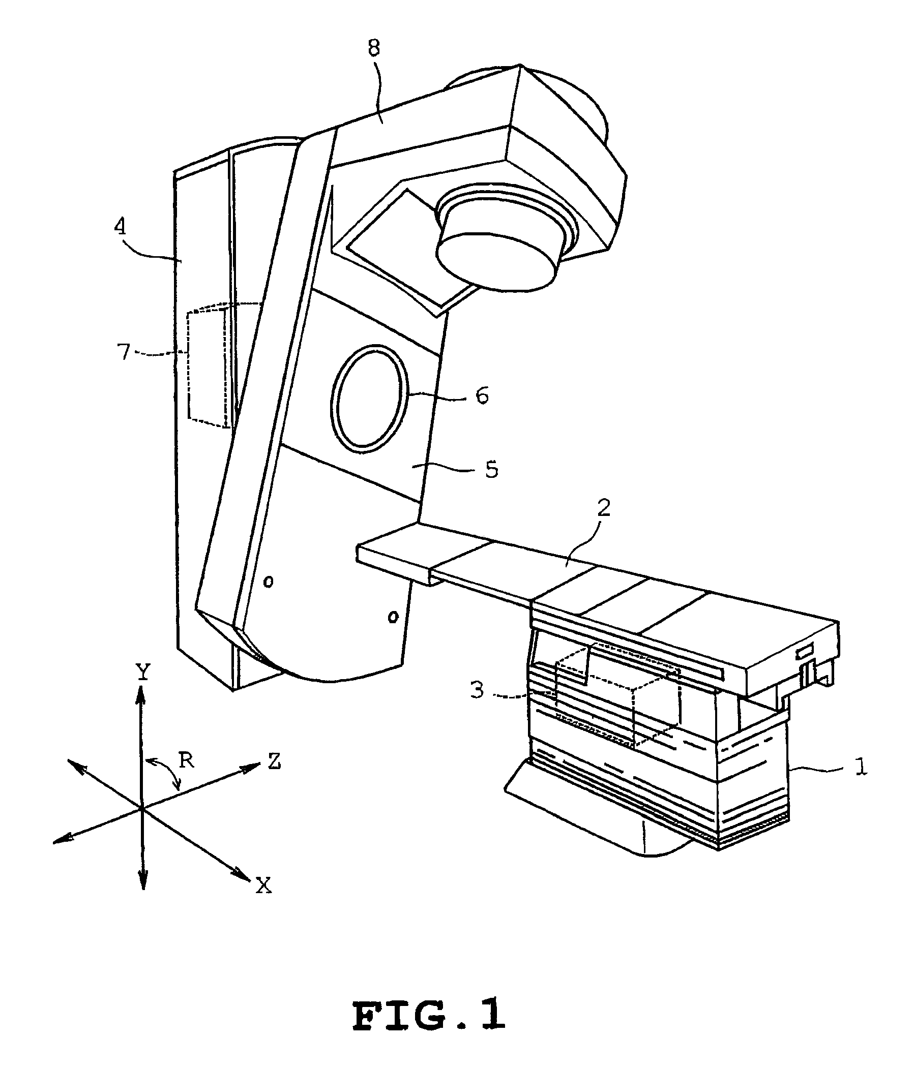
[0019]the present invention will be described with reference to FIGS. 1 to 6. Referring to FIG, 1, a radiation treatment machine or radiotherapy machine is shown to which the multileaf collimator of the invention is applied. The radiation treatment machine includes a stand 1 having an upper end on which a horizontal treatment table 2 extending in the X direction is mounted as shown in FIG. 1. A patient is to be put on the treatment table 2 so that the head and legs of the patient are directed in the X direction for the purpose of medical treatment. The treatment table 2 is connected to an XY drive mechanism including an X-direction motor and a Y-direction motor both serving as drive sources. The XY drive mechanism is housed in the stand 1. An amount of rotation of the X-direction motor is controlled so that the treatment table 2 is moved to a horizontal X-direction target position. An amount of rotation of the Y-direction motor is controlled so that the treatment table 2 is moved to...

second embodiment

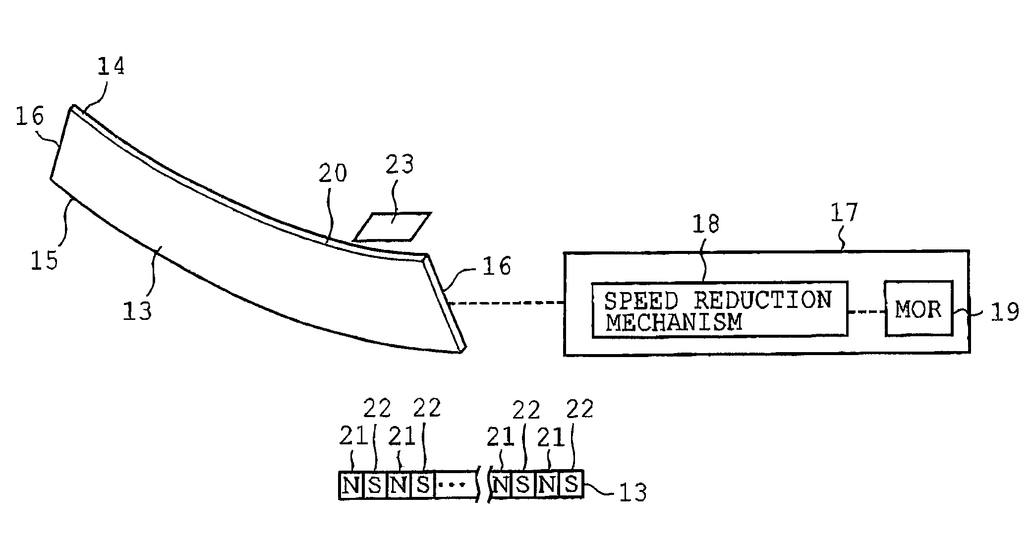
[0040]FIG. 7 illustrates the invention. Each leaf block 13 has a plurality of convex portions 41 and a plurality of concave portions 42 alternately formed on the overall arc-shaped face 14 as shown in FIG. 7. The convex portions 41 are circumferentially arranged at regular intervals and have the same circumferential dimension. The concave portions 42 are arranged circumferentially at regular intervals and have the same circumferential dimension as the concave portions 41.

[0041]The magnetic layers 20 are formed on the leaf blocks 13 so as to be located on the entire arc-shaped faces 14 respectively. Each magnetic layer 20 is formed by applying a powdered magnetic material to the arc-shaped face 14 from over the convex and concave portions 41 and 42. The magnetized portion 21 magnetized in the north pole and the magnetized portion 22 magnetized in the south pole are located on the surface of each convex portion 41. Also, the magnetized portion 21 magnetized in the north pole and the m...


PUM


Abstract

A multileaf collimator includes a first leaf block group including plural leaf blocks, a second leaf block group including plural leaf blocks arranged in the same direction as the first leaf block group and disposed opposite the leaf blocks of the first leaf block group, plural magnetic layers located on the respective leaf blocks of the first and second leaf block groups so as to be positioned on faces of the leaf blocks along a moving direction of the leaf blocks, plural magnetic sensors mounted on the respective leaf blocks and varying output signals when the respective leaf blocks are moved in an oncoming direction or a departing direction, and a control device controlling drive mechanisms according to the output signals delivered by the respective magnetic sensors so that spacing between the leaf blocks of the first and second leaf blocks is adjusted into a target configuration.

Description

CROSS-REFERENCE TO RELATED APPLICATIONS[0001]This application is based upon and claims the benefit of priority from the prior Japanese Patent Application No. 2007-245730 filed on Sep. 21, 2007, the entire contents of which are incorporated herein by reference.BACKGROUND OF THE INVENTION[0002]1. Field of the Invention[0003]The present invention relates to a multileaf collimator which adjusts radiation irradiated from a radiation generator toward a patient into a shape according to an affected part of the patient.[0004]2. Description of the Related Art[0005]One type of conventional multileaf collimator includes first and second groups disposed opposite to each other. Each group includes a plurality of leaf blocks arranged in a direction. The leaf blocks of the first group are oppositely disposed so as to be perpendicular to the leaf blocks of the second group The leaf blocks of the first group are connected to a drive mechanism having an electric motor serving as a drive source so tha...

Claims


Application Information

Patent Timeline
Patent Type & Authority Patents(United States)
IPC IPC(8): G21K1/04
CPCG21K1/046G21K1/04A61N5/1042
Inventor HASEGAWA, YUKIHISAAWAZU, MINORU
Owner KK TOSHIBA
Why Eureka
Try Eureka