Cardiac CT system and method for planning atrial fibrillation intervention

a technology of atrial fibrillation and imaging system, which is applied in the field of cardiac implant systems, can solve the problems of complex 3d geometry of the left atrium and pvs, tissue vaporization and surface charring, and pv stenosis

Active Publication Date: 2009-07-21
GE MEDICAL SYST GLOBAL TECH CO LLC +1
View PDF69 Cites 194 Cited by
  • Summary
  • Abstract
  • Description
  • Claims
  • Application Information

AI Technical Summary

Benefits of technology

[0005]The above discussed and other drawbacks and deficiencies of the prior art are overcome or alleviated by a method for planning atrial fibrillation (AF) intervention for a patient. In an exemplary embodiment, the method includes obtaining acquisition data from a medical imaging system, and generating a 3D model of the left atrium and pulmonary veins of the patient. One or more left atrial (LA) and pulmonary vein (PV) anatomical landmarks are identified on the 3D model, and saved views of the 3D model are registered on an interventional system. One or more of the registered saved views are visualized with the interventional system.
[0006]In another aspect, a method for planning atrial fibrillation (AF) intervention for a patient includes obtaining acquisition data from a medical imaging system using a protocol directed toward the left atrium and pulmonary veins. The acquisition data is segmented using a 3D protocol so as to visualize the left atrium and pulmonary veins. A 3D model of the left atrium and pulmonary veins of the patient is generated, and one or more left atrial (LA) and pulmonary vein (PV) anatomical landmarks on the 3D model are identified. Saved views of the 3D model are registered on an interventional system, and one or more of the registered saved views are visualized the interventional system. Levels of ablation to be applied to a specific area of one or more LA and PV surfaces are identified from the 3D model.
[0007]In still another aspect, a method for planning atrial fibrillation (AF) intervention for a pati

Problems solved by technology

Locally, temperatures above 100″ C can occur causing tissue vaporization and surface charring which could be disastrous in areas such as the inside of the PVs.
However, even temperatures above 50″ C are also likely to cause PV stenosis.
However, such identification is possible in only a few patients.
In addition t

Method used


Image

  • Cardiac CT system and method for planning atrial fibrillation intervention
  • Cardiac CT system and method for planning atrial fibrillation intervention
  • Cardiac CT system and method for planning atrial fibrillation intervention

Examples


Embodiment Construction

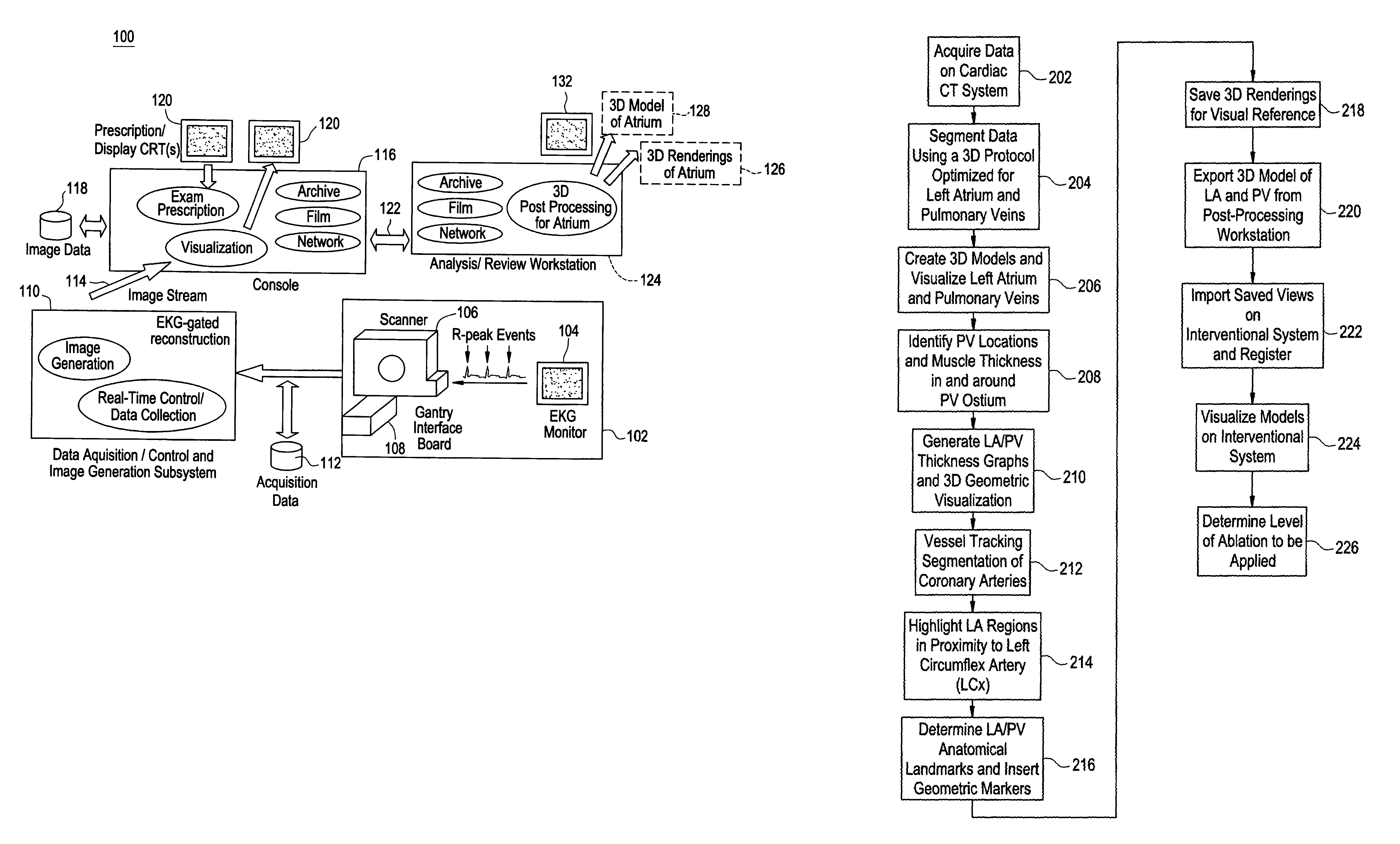
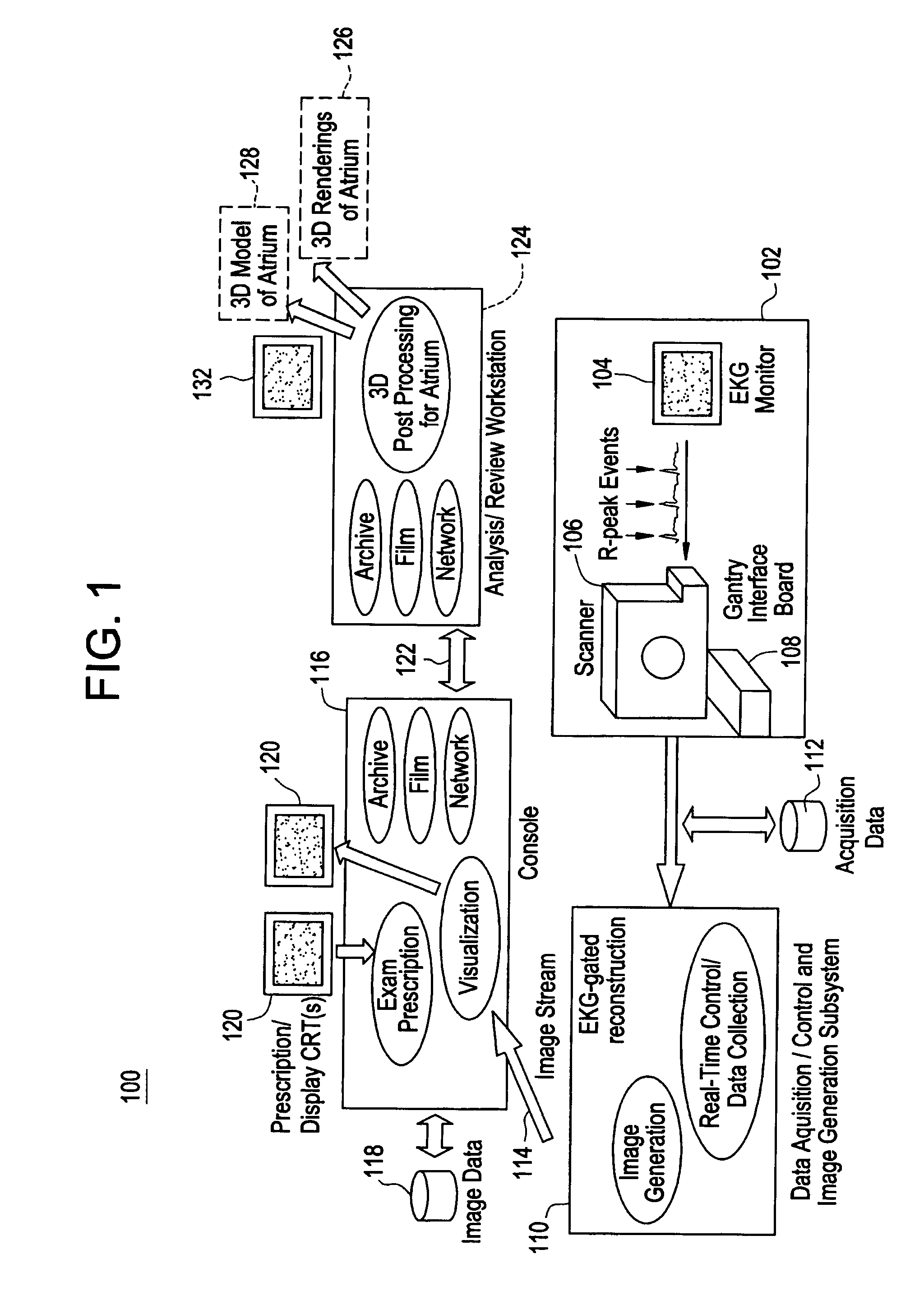
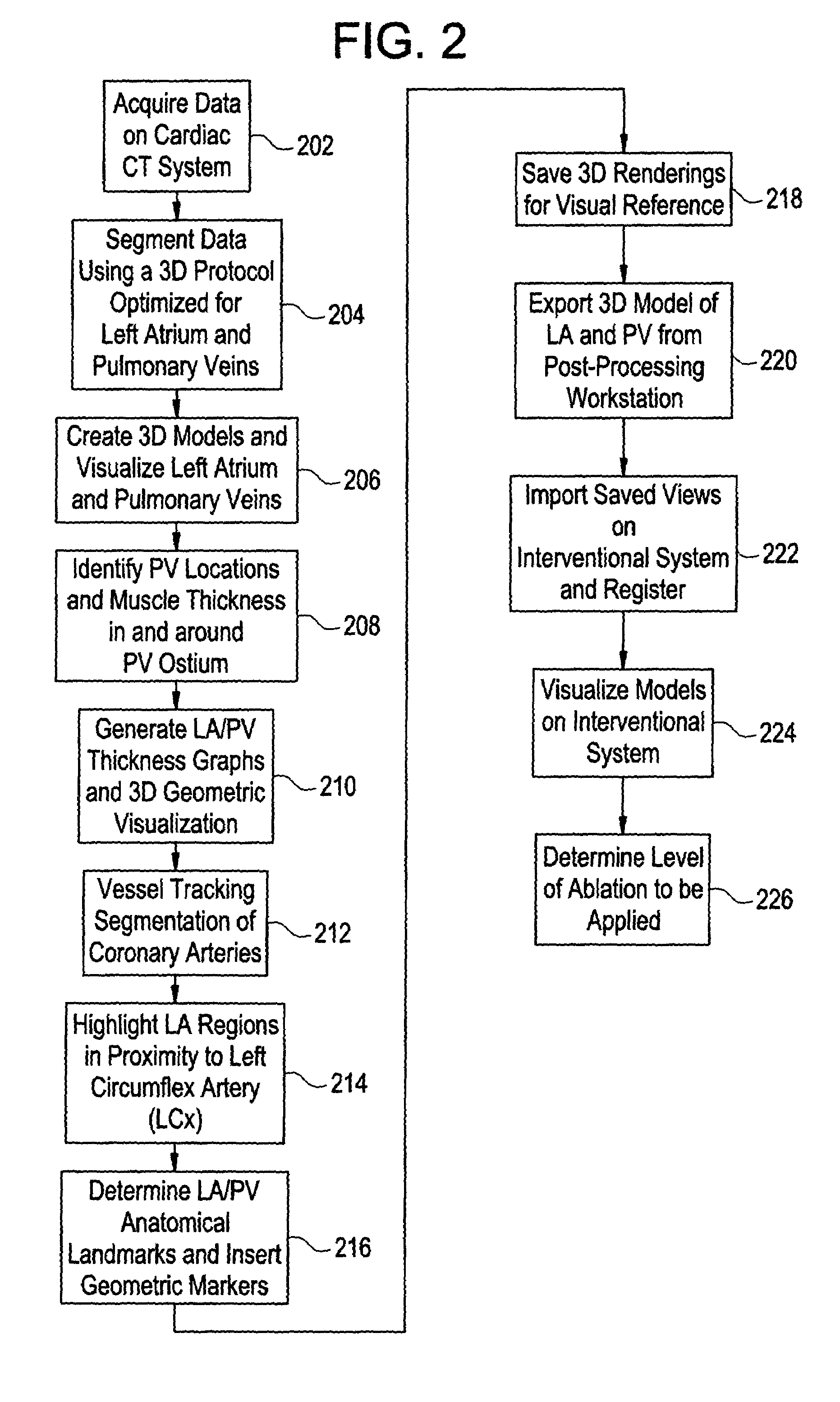
[0013]Disclosed herein is a cardiac imaging system and method for atrial fibrillation (AF) ablation that provides information for planning interventional procedures that enable an electrophysiologist, cardiologist and / or surgeon to plan in advance a desired approach to take for the procedure. Additionally, with a more detailed three-dimensional (3D) geometrical representation of the left atrium (LA) and pulmonary veins (PV), as may be obtained from imaging modalities such as computed tomography (CT), magnetic resonance (MR) and ultrasound, the practitioner can identify the location and orientation of PVs and muscle thickness in and around the PV ostium, as well as at other strategic locations. The degree and location of applied RF energy may be selected beforehand so as to avoid the problems encountered with ablation procedures, thereby making the procedure more efficacious and reducing the risk of complications such as PV stenosis.

[0014]Although the exemplary embodiments illustrate...


PUM


Abstract

A method for planning atrial fibrillation (AF) intervention for a patient includes obtaining acquisition data from a medical imaging system, and generating a 3D model of the left atrium and pulmonary veins of the patient. One or more left atrial anatomical landmarks are identified on the 3D model, and saved views of the 3D model are registered on an interventional system. One or more of the registered saved views are visualized with the interventional system.

Description

BACKGROUND OF THE INVENTION[0001]The present disclosure relates generally to cardiac implant systems and, more particularly, to a cardiac imaging system and method for planning atrial fibrillation intervention.[0002]Atrial fibrillation (AF) is an arrhythmia in which the atria (upper chambers of the heart) stop contracting as they fibrillate, and is the most common of heart rhythm problems. It is estimated that over 2.2 million Americans have AF. Because of the role of the pulmonary veins (PVs) in generating AF, a variety of surgical and catheter techniques have been used to isolate the PVs from the left atrium using energy sources such as radiofrequency (RF) energy. In addition to PV isolation, several other strategic targets, such as the mitral valve to left inferior PVs, can be targeted to improve efficacy. Transmural lesions formed during ablation are advantageous, as discontinuous lines may allow AF breakthrough or potential development of other arrhythmias such as atrial flutte...

Claims


Application Information

Patent Timeline
IPC IPC(8): A61B5/05A61B6/00A61B19/00A61N1/08G06F19/00
CPCA61B6/503G06F19/3437A61B5/7285A61B6/504A61B6/541A61B19/50A61N1/08G06F19/321A61B8/543A61B34/10G16H30/20G16H40/63G16H50/50
Inventor OKERLUND, DARIN R.SRA, JASBIR S.THOMSON, HELEN
Owner GE MEDICAL SYST GLOBAL TECH CO LLC
Why Eureka
Try Eureka