Torque-angle instrument

a technology of torque-angle and wrench, which is applied in the direction of wrenches, screwdrivers, force/torque/work measurement apparatus, etc., can solve the problems of component failure, poor method of torque measurement, and mechanical reference to a stationary point, etc., and achieves structural and operating advantages

Active Publication Date: 2009-07-28
SNAP ON INC
View PDF25 Cites 51 Cited by
  • Summary
  • Abstract
  • Description
  • Claims
  • Application Information

AI Technical Summary

Benefits of technology

[0013]There is disclosed herein a torque-angle instrument, such as a wrench, including a method of operation, for measuring applied torque and applied angle to a work-piece which avoids the disadvantages of prior devices while affording additional structural and operating advantages.

Problems solved by technology

However, torque measurement is a poor method of determining ‘bolt load,’ because variations in frictional components vary the ‘bolt load’ achieved for a given torque applied.
The disadvantages of these devices is that they require mechanical reference to a stationary point.
This requires repositioning the reference arm for every fastener to be tightened, and a poorly positioned arm could cause gross errors in measurement, perhaps leading to component failure.
Still other similar devices come at a very high price (>US$1,200) and include complex menu-driven operation, which in some markets, such as automotive, may be prohibitive.

Method used


Image

  • Torque-angle instrument
  • Torque-angle instrument
  • Torque-angle instrument

Examples


Embodiment Construction

[0037]While this invention is susceptible of embodiments in many different forms, there is shown in the drawings and will herein be described in sufficient detail a preferred embodiment of the invention with the understanding that the present disclosure is to be considered as an exemplification of the principles of the invention and is not intended to limit the broad aspect of the invention to the embodiment illustrated.

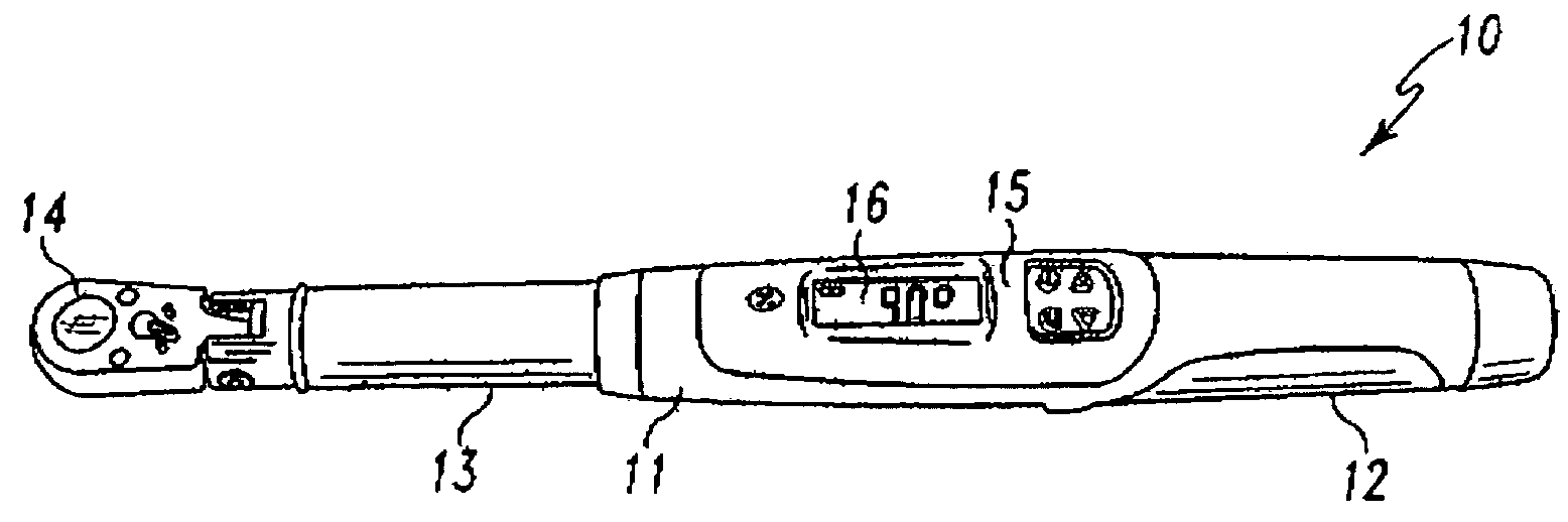
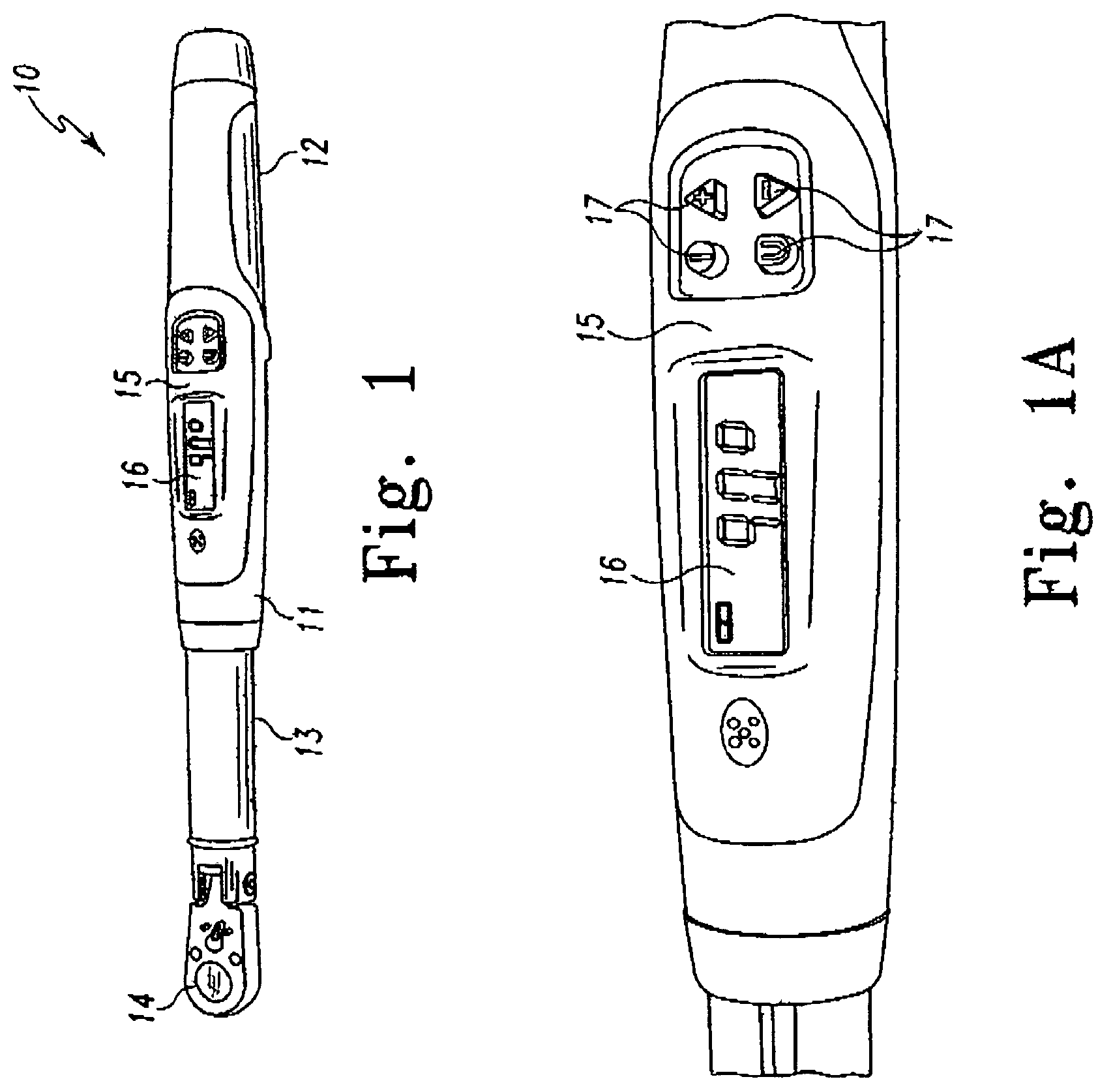
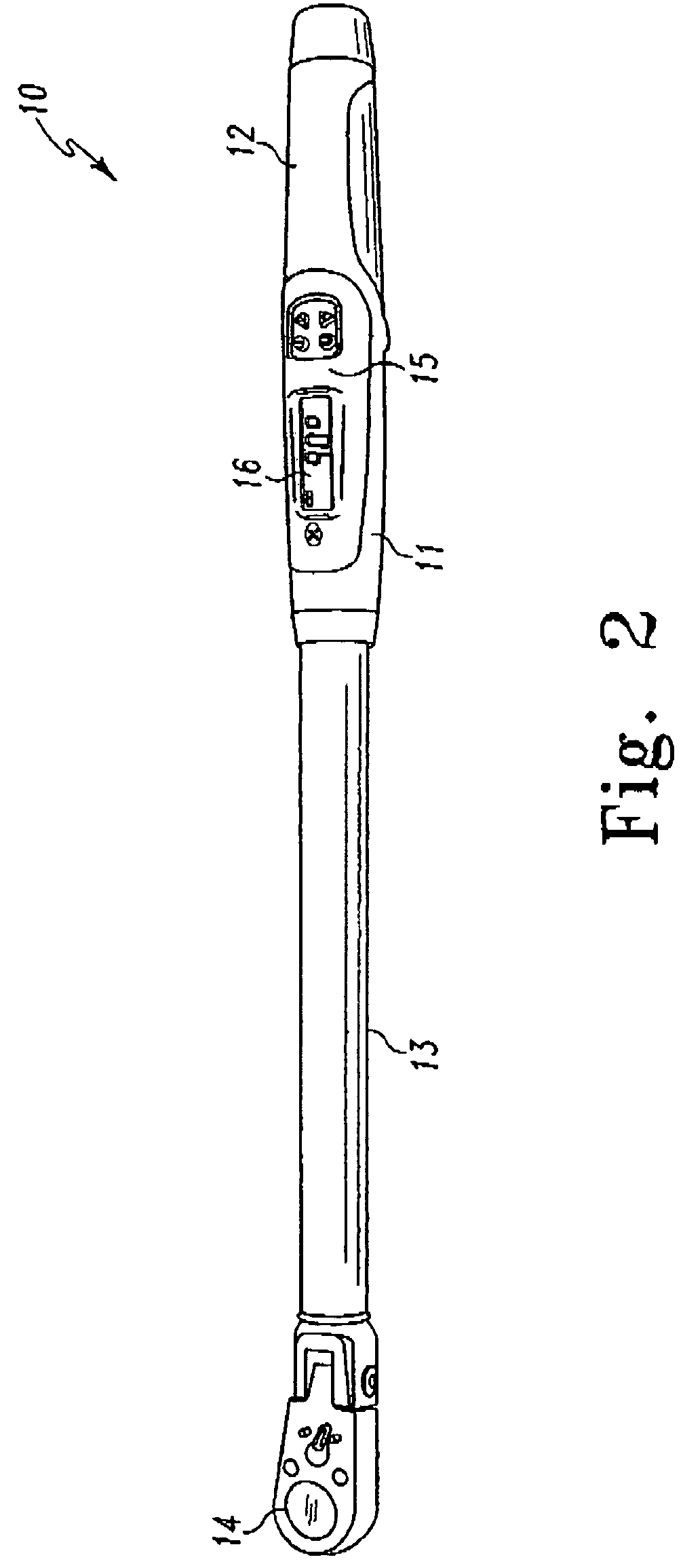
[0038]The present application discloses a wrench that measures both torque and angle of rotation. It allows the tool user to perform bolt-tightening jobs requiring angle specifications with a single tool. A vibrating handle and audible tone alert the user when the measured torque or angle reaches a user-selected preset value.

[0039]With reference to U.S. Pat. No. 5,589,644 entitled “Torque-Angle Wrench,” the instrument described herein implements a number of software features that utilize and facilitate the measurement of torque and angle, individually and simultaneou...


PUM


Abstract

An electronic torque-angle instrument including a generally tubular body having a gripping section and a pivoting head for engaging a workpiece, such as a nut or bolt, and a housing associated with the body and containing electronics, including a microprocessor, which permit individual or simultaneous measurement of torque and angle applied to the workpiece. The microprocessor includes stored programs which interpret a signal from an input, such as a gyroscopic sensor, and sends the interpreted signal to an output means. The signal is finally displayed as an accurate torque measure and / or angle measure from the output means.

Description

RELATED APPLICATION[0001]This application is related to and claims the filing priority of U.S. Provisional Application No. 60 / 740,085, filed on Nov. 28, 2005 and entitled “Torque-Angle Instrument”. The '085 application is hereby incorporated by reference.BACKGROUND OF THE INVENTION[0002]1. Field of the Invention[0003]This application relates to wrenching tools and, specifically, to torque-angle measuring and recording wrenches.[0004]2. Description of the Prior Art[0005]The object of a wrenching tool is to rotate or hold against rotation an item, such as a threaded fastener (e.g. a bolt) joining two objects together. As the fastener is tightened it is stretched until it exerts the appropriate amount of compression force (called “bolt load”) to the objects being held together or in place by the bolt. There is a relationship between the amount of torque that is applied to the head of a fastener and the amount of load applied to the joined objects. However, torque measurement is a poor ...

Claims


Application Information

Patent Timeline
Patent Type & Authority Patents(United States)
IPC IPC(8): B25B23/14
CPCB25B23/1425
Inventor CRASS, MATTHEW M.BECKER, THOMAS P.MARQUETTE, MATTHEW S.HACKL, RICHARD J.BEYERL, PAUL J.THORELL, MARVIN D.
Owner SNAP ON INC
Why Eureka
Try Eureka