
Burner assembly

a burner and burner technology, applied in the field of burners, can solve the problems of affecting the operation of the burner assembly, compromising the burner's efficiency, and the flame being lifted from the burner nozzle,

Active Publication Date: 2009-07-28
ACL MFG
View PDF5 Cites 17 Cited by
  • Summary
  • Abstract
  • Description
  • Claims
  • Application Information

AI Technical Summary

Benefits of technology

The solution provides a stable and efficient flame in both low and high fire conditions, eliminates the need for manual lighting, and prevents freezing, achieving 7-10% higher efficiency compared to natural draft burners and operating effectively across a wide pressure range.

Problems solved by technology

The secondary air, intended to aid in combustion, may adversely affect the operation of the burner assembly.
Large volumes of secondary air creating a large turbulent draft at the burner head may result in the flame being lifted from the burner nozzle or may blow out a flame at the nozzle.
Attempts to reduce or dampen the amount of secondary air entering the burner can substantially shutoff the flow of secondary air which compromises the efficiency of the burner.
Further, variability in operation can adversely affect the consistency of ignition and flame sensing.
Thus, in conventional burners, ignition and flame sensing, which are optimized for one flame characteristic, become problematic as the position of the flame alters.
In variable firing conditions, should the fuel / air ratio and secondary air flow be sufficiently unstable at the burner nozzle, remote lighting of the burner becomes difficult.
As a result, the industry has typically relied on manual lighting of such burners which has resulted in significant hazard to personnel performing the task.
Additionally, freezing is a common problem with natural draft burner assemblies.
Typically, areas of low pressure adjacent the orifice of the burner may result in freezing at the orifice or in the gas lines which feed the orifice.
Low flow of fuel at pilot assemblies are even more prone to freezing

Method used


Image

  • Burner assembly
  • Burner assembly
  • Burner assembly

Examples


Embodiment Construction

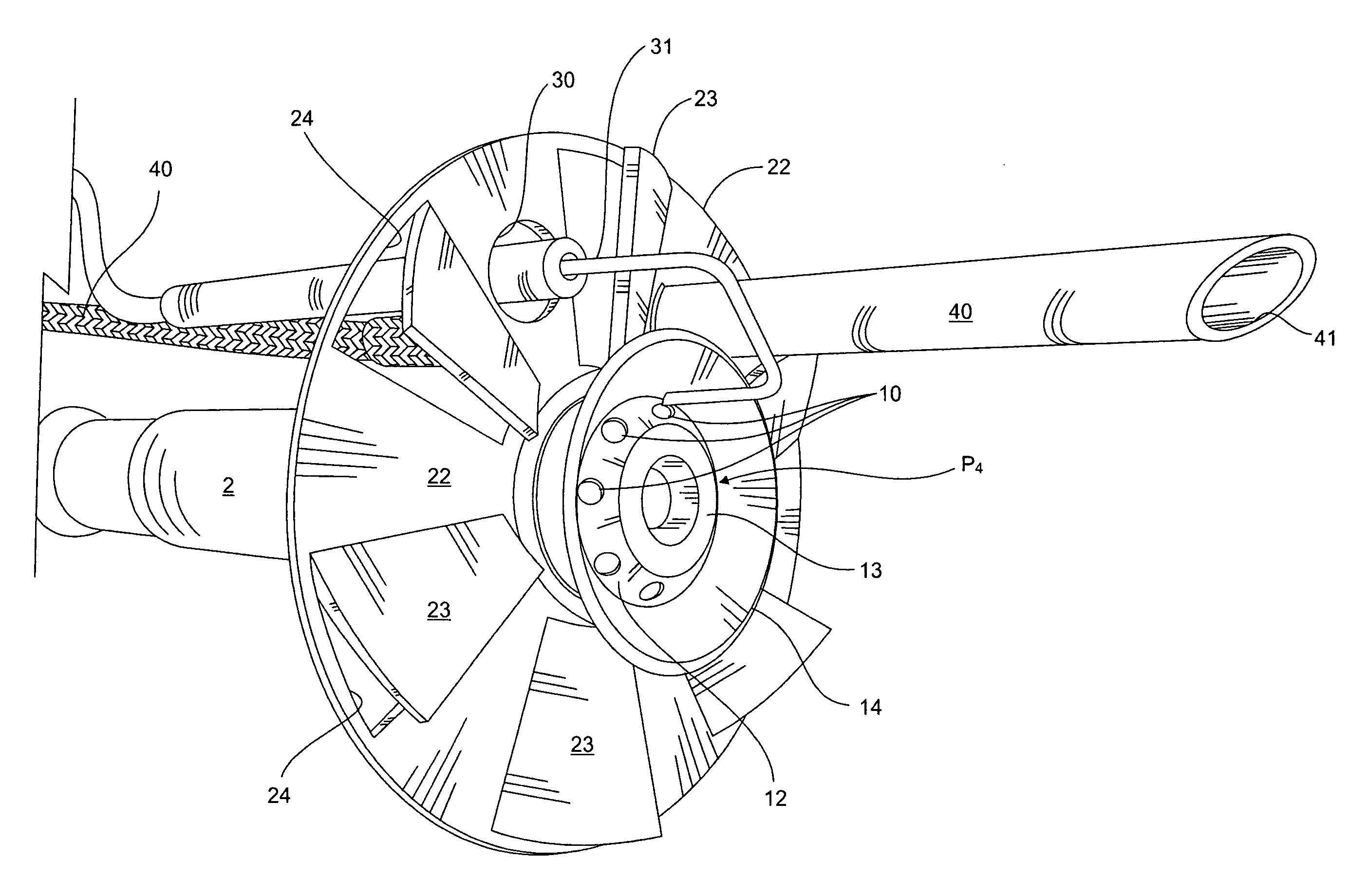
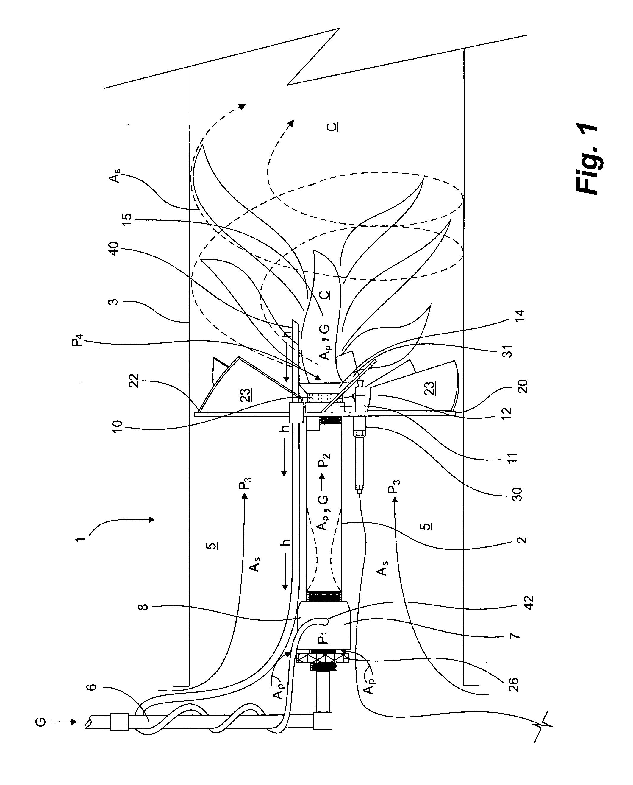
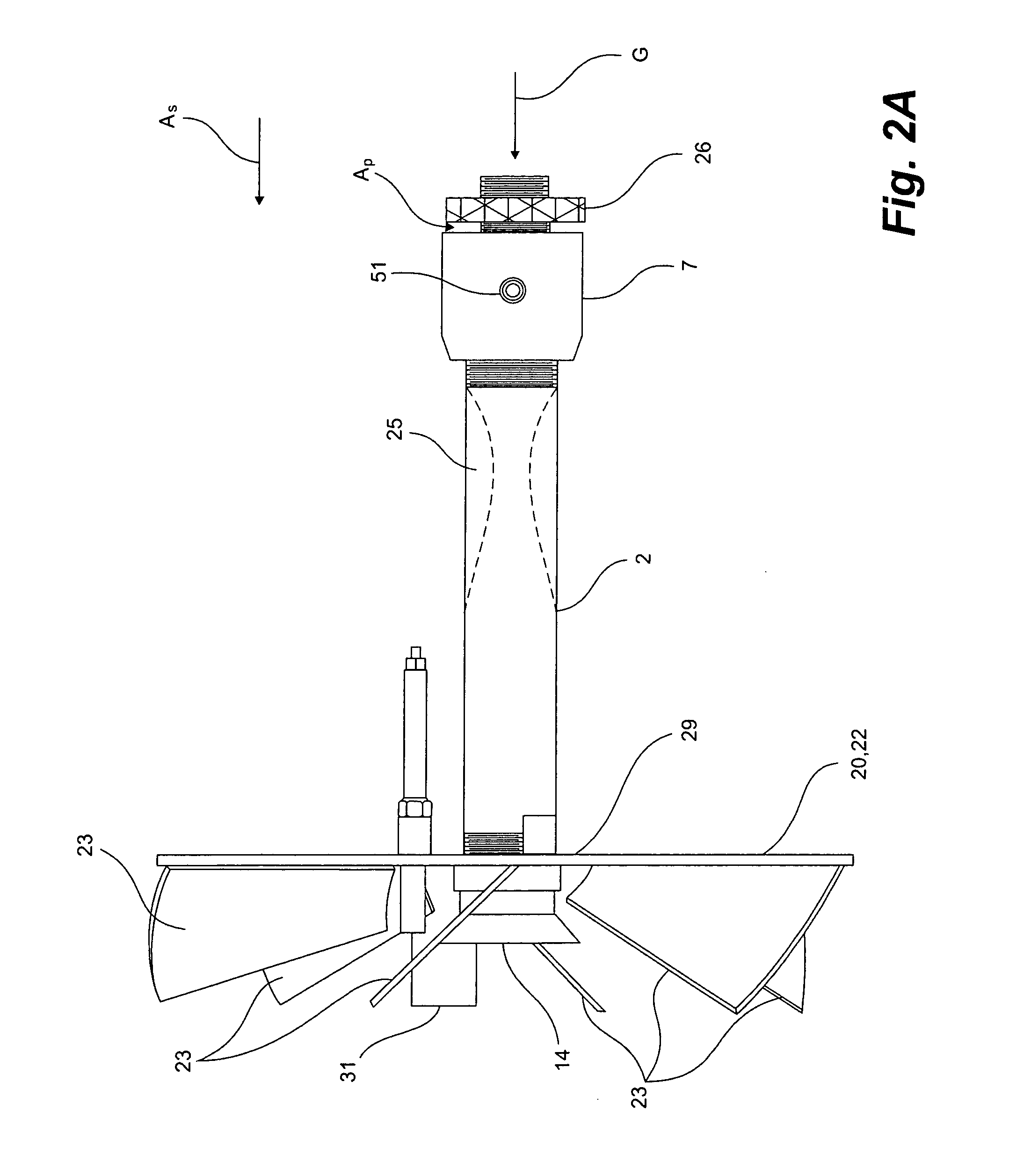
[0019]Having reference to FIGS. 1-8, a burner assembly 1 according to an embodiment of the invention is shown.

[0020]As shown in FIG. 1, the burner assembly 1 comprises a tubular barrel 2 which is mounted in the bore of a firetube or other such housing 3, forming an annulus 5 therebetween. The tubular barrel 2 conducts primary fuel gas G from a gas inlet 6 at a base or proximal end 8 of the tubular barrel 2 to a burner head 12 at a distal end 11 of the tubular barrel 2. The barrel 2 is typically of conventional configuration. The gas at the gas inlet 6 is fed at a first pressure P1 through an orifice 50 to a mixer head 7 (FIGS. 5, 7 and 8) at the proximal end 8. Primary combustion air Ap is drawn into the mixer head 7 via natural draft and the combined air Ap and gas G are mixed therein and flow through the tubular barrel 2 at a second pressure P2 to an orifice or plurality of orifices 10 in the burner head 12. The air and gas discharge from the burner head 12 at a nozzle tip 13 and,...


PUM


Abstract

A burner assembly has a burner head and a deflector plate extending radially therefrom and across a firetube housing for supporting the burner assembly therein. The deflector plate has a plurality of angled vanes for re-directing secondary combustion air flowing through the housing. Secondary air is deflected away from a nozzle tip at the burner head to minimize lifting of the flame by the deflector plate or by a low pressure ring formed around the nozzle tip above the deflector plate for creating an area of low pressure. Preferably, a combination of the deflector plate and low pressure ring provides a stable flame positioned at the nozzle tip under low-fire and high-fire conditions enabling use of a pilotless ignition and flame sensing system which is consistent under low and high fire conditions. More preferably, the deflector plate supports the igniter and optionally a heat return tube for heat tracing of the freeze-prone burner assembly components.

Description

FIELD OF THE INVENTION[0001]The present invention relates to the field of burners and particularly to gas burners used in industrial heaters.BACKGROUND OF THE INVENTION[0002]It is well known in a variety of industries to use heaters having burner assemblies for a number of different applications, including kilns, drying apparatus, furnaces and for preventing freezing of tanks and pipelines. In the oil and gas industry, heaters are particularly used in regions where low ambient temperatures may result in freezing of storage tanks or in production and process pipelines. Further process heaters are used which may be used when knocking water out of oil and when heating salt baths and the like. Gas burner assemblies are typically arranged in a housing or firetube which extends into a storage or holding tank to be heated.[0003]In prior art natural draft or “non-forced draft” situations, primary combustion air is drawn into a mixing chamber or mixer head of the gas burner assembly as a res...

Claims


Application Information

Patent Timeline
Patent Type & Authority Patents(United States)
IPC IPC(8): F23M9/00
CPCF23C3/002F23C6/045F23C7/006F23C9/00F23D14/66F23D14/08F23D14/60F23C2900/06041F23C2202/10Y02E20/34
Inventor ALDRICH, CHRIS
Owner ACL MFG
Learn More