Wind turbines

a technology of wind turbines and blades, applied in the direction of propellers, engine control parameters, and avoiding excessive blade deflection, can solve the problems of blade tip displacement, blade blade and tower collision, and reduce performance, so as to increase the tip-to-tower distance, reduce lift, and increase the speed of the rotor

Active Publication Date: 2013-07-25
VESTAS WIND SYST AS
View PDF8 Cites 15 Cited by
  • Summary
  • Abstract
  • Description
  • Claims
  • Application Information

AI Technical Summary

Benefits of technology

[0017]Supporting the pressure-sensing device by means of the tower allows the pressure-sensing device to be positioned within the wake of the rotor at a level corresponding to the lower half of the rotor disc. The signal from the pressure-sensing device may be transformed into signals indicative of wind speed and wind direction at the tower, within the wake of the rotor at a level corresponding to the lower half of the rotor disc. Suitable filtering and / or correction may be applied to the signals to remove turbulent effects caused by the rotor, in order to arrive at the ambient wind speed and wind direction at the tower. Knowledge of these parameters allows more sophisticated rotor-control algorithms to be employed.
[0033]The controller may be configured to take action to increase the clearance between the blades and the tower if that clearance approaches or falls below a predefined minimum value or if the probability of a collision between a blade and the tower exceeds a predetermined maximum acceptable value. For example, the controller may be configured to introduce or vary a cyclic pitch pattern to reduce the lift generated by the lower part of the rotor disc.

Problems solved by technology

As the blades are long, in excess of 50 metres in many cases, any flexing or bending of the blades may translate into considerable displacement of the tips of the blades out of the rotor disc in the wind direction.
Flexing of the blades in this way presents a risk of a collision between the blades and the tower in extreme conditions.
Excessive pre-bending, tilt and coning can reduce the performance and hence reduce the efficiency of the wind turbine.
In addition, excessive pre-bending can make blades difficult to manufacture and problematic to transport.
Furthermore, increasing the rigidity of the blades generally means increasing the weight of the blades and hence increasing the size and weight of other wind turbine components that must support the heavier blades.
This increases the cost of the wind turbine and may further reduce its performance and efficiency.

Method used


Image

  • Wind turbines
  • Wind turbines
  • Wind turbines

Examples


Embodiment Construction

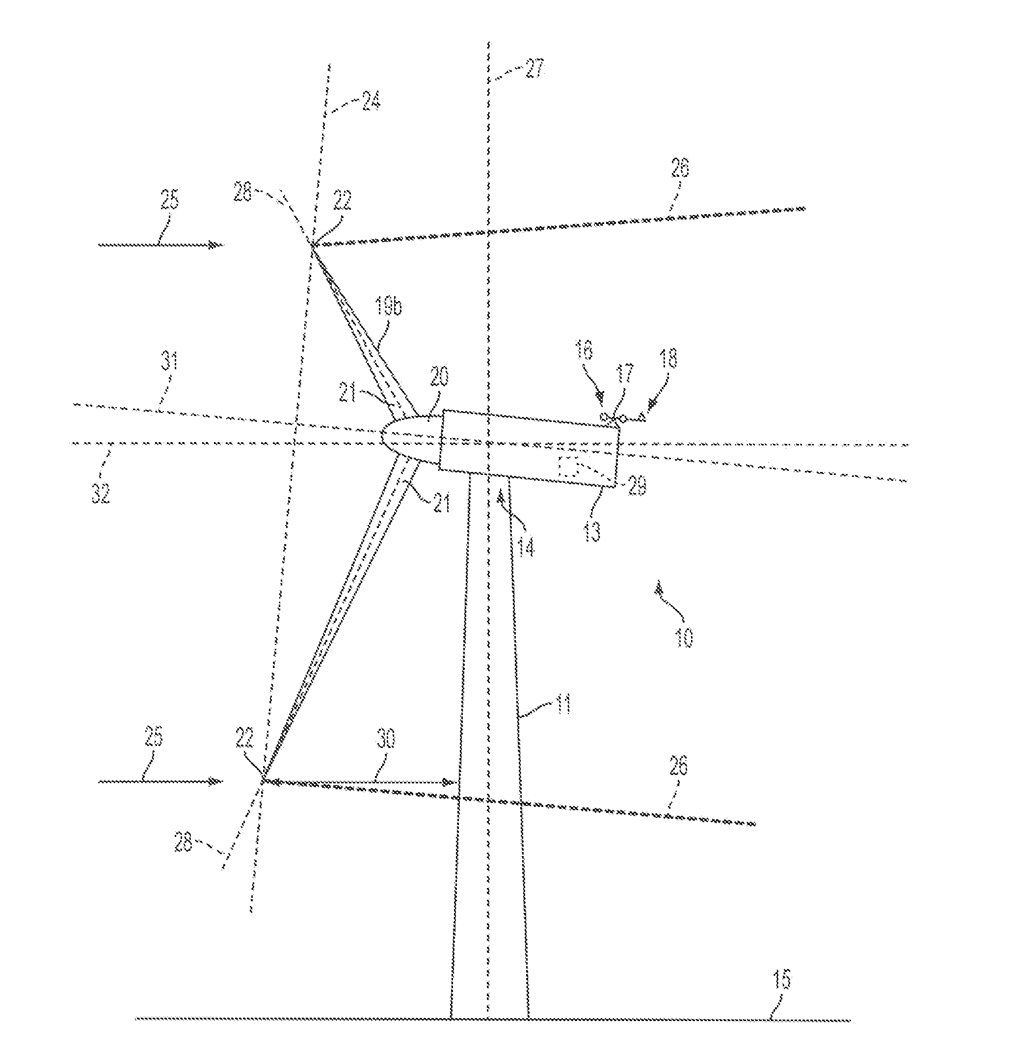
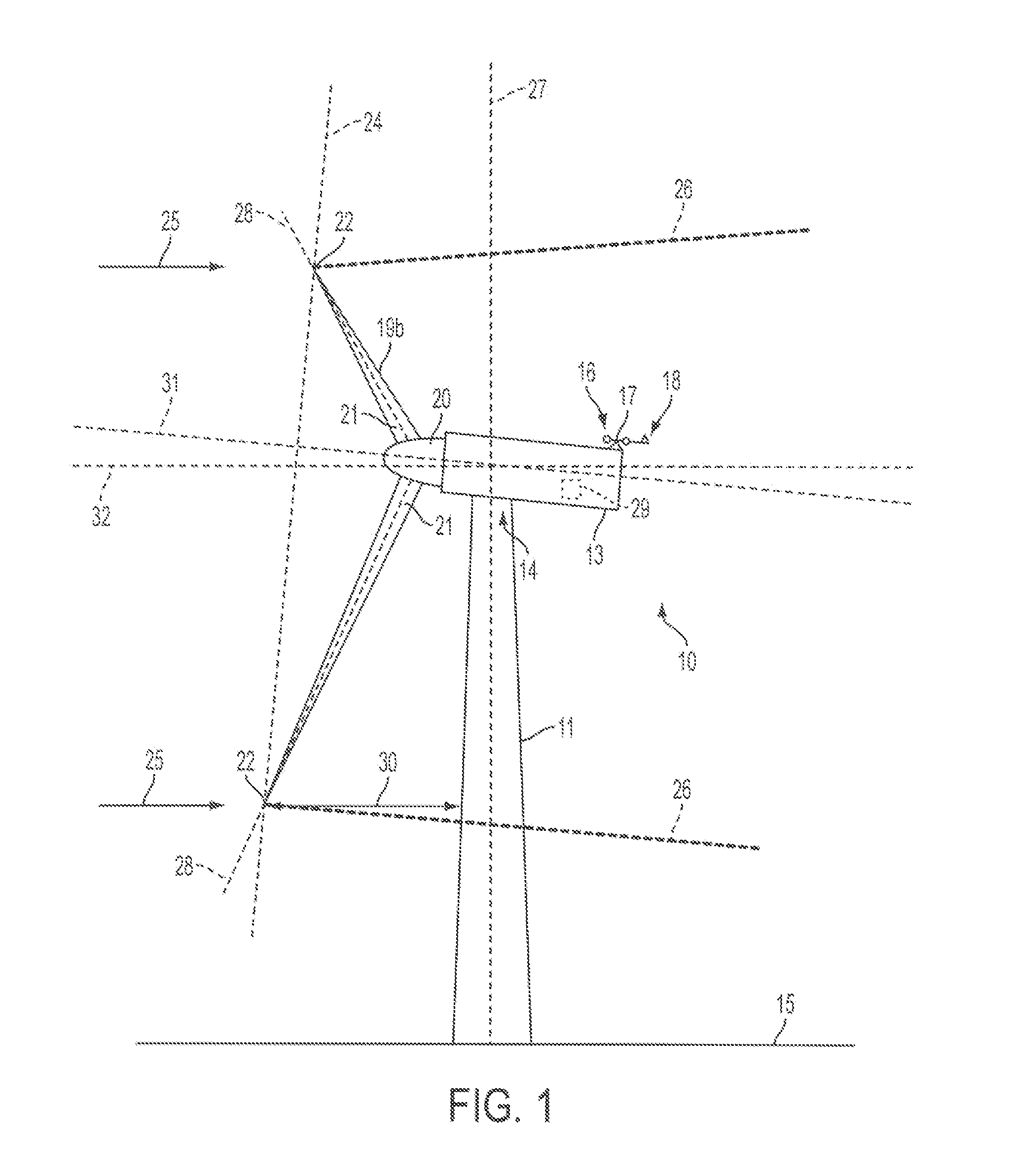
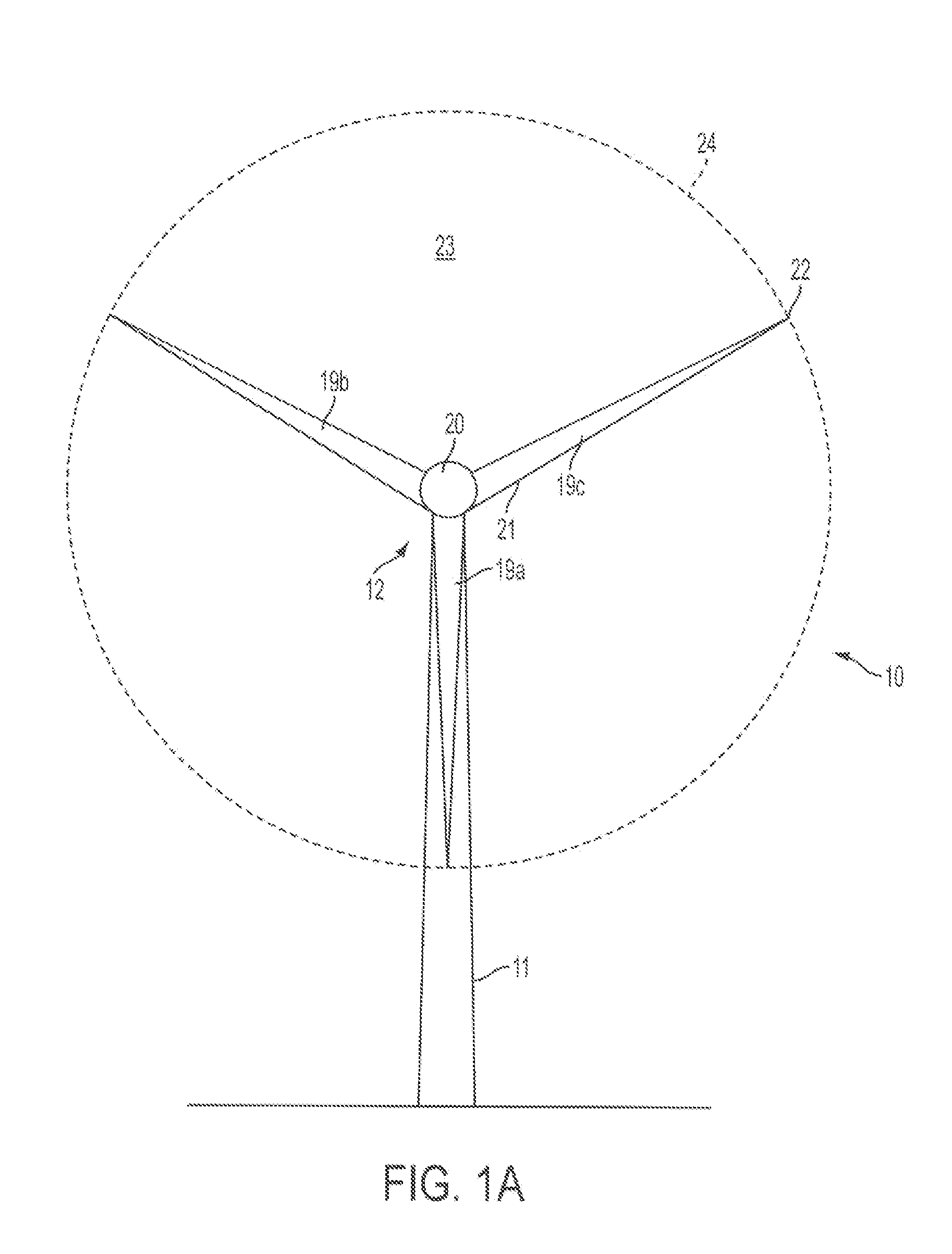
[0043]FIG. 2 shows a horizontal axis upwind wind turbine 100 comprising a tubular tower 102 supporting a nacelle 104 at its upper end 106. The nacelle 104 in turn supports a rotor 108, which includes three equally-spaced rotor blades 110a, 110b, 110c extending radially from a central hub 112 when viewed from the front as shown in FIG. 4. Again, only two blades 110a, 110b are shown in the side view of FIG. 2. A wind-monitoring device 114 including an anemometer 115 and a vane 116 is mounted above the nacelle 104. The anemometer 115 monitors wind speed, whilst the vane 116 monitors wind direction above the tower 102 within the wake 117 (FIG. 2) of the rotor 108 corresponding to an upper half of the rotor disc 118. The upper half of the rotor disc 118 is the semi-circular region 119 above the horizontal dashed line 120 in FIG. 4.

[0044]A pressure-sensing device 121 comprising an array of sensors 122 is arranged at an outer surface 124 of the tubular tower 102 within the wake 117 of the ...


PUM


Abstract

An upwind wind turbine comprising a tower and a rotor is described. The wind turbine additionally includes a pressure-sensing device supported by the tower at a location within the wake of the rotor. The pressure-sensing device is configured to sense air pressure and provide a signal indicative of the sensed air pressure to a wind turbine controller for use in controlling the rotor of the wind turbine.

Description

TECHNICAL FIELD[0001]The present invention relates to wind turbines and the control of wind turbines.BACKGROUND[0002]By way of background to the present invention, FIG. 1 and FIG. 1A show a prior art horizontal axis wind turbine 10 comprising a tower 11, a rotor 12 and a nacelle 13. The nacelle 13 is supported at an upper end 14 of the tower 11, which can be 100 metres above ground level 15 for a multi-megawatt turbine. The nacelle 13 houses the rotor shaft, generator and gearbox (if present). A wind-monitoring device 16 is located on top of the nacelle 13. The wind-monitoring device 16 includes an anemometer 17 for monitoring wind speed and a vane 18 for monitoring wind direction in a horizontal plane.[0003]The rotor 12 is supported by the nacelle 13 and includes three rotor blades 19a, 19b, 19c. Only two blades 19a, 19b are shown in the side view of FIG. 1. However, all three blades 19a, 19b, 19c can be seen in the front view of FIG. 1A. Referring to FIG. 1A, the blades 19a, 19b, ...

Claims


Application Information

Patent Timeline
Patent Type & Authority Applications(United States)
IPC IPC(8): F03D7/02
CPCF03D7/0224F03D7/0288F05B2240/2022F05B2270/17Y02E10/723F05B2270/321F05B2270/324F05B2270/33F05B2270/32Y02E10/72F05B2260/80F05B2270/301G01P5/165
Inventor WEDEL-HEINEN, JENS JAKOB
Owner VESTAS WIND SYST AS
Why Eureka
Try Eureka