System and method for network topology discovery

a network topology and network technology, applied in the field of computer systems and networks, can solve problems such as failure of computer systems, network elements at fault, and techniques applicable to one effort not necessarily transferable to others

Inactive Publication Date: 2009-07-28
MICROSOFT TECH LICENSING LLC
View PDF11 Cites 45 Cited by
  • Summary
  • Abstract
  • Description
  • Claims
  • Application Information

AI Technical Summary

Benefits of technology

[0012]Briefly, the present invention provides a method and system for discovering the topology of an Ethernet network of computers and other elements, which using the taxonomy described above, is active, collaborative (of the computer systems), operates at the data-link layer, and does not require any support from the network elements. Using only the computer systems of a network, the method and system provide significant detail of the network, without needing support from the network elements. Network topology information is thus provided which previously was unavailable. This information, possibly in conjunction with that discovered by prior techniques, can provide substantial benefits and advantages.

Problems solved by technology

However, the techniques applicable to one effort are not necessarily transferable to others.
For example, if the computers attached to some network element become uncommunicative simultaneously, it is likely to be the network element that is at fault, rather than a correlated failure of the computer systems.
However these MIBs may only contain information on recently active hosts, since bridges timeout their port filtering tables after around five minutes.
Another feature of these management interfaces is that there is some variance in how they are implemented, although they are supposed to be standardized.
One reason for this is that in many cases, no one has control over the hardware with respect to being able to automatically identify the equipment and its capabilities.
Even if new standards are implemented with respect to hardware that does identify itself and its capabilities, there will still remain large quantities of legacy Ethernet network equipment in circulation.
Moreover, inexpensive switches and hubs (e.g., for home networking or small business use) will likely never implement such complex behavior, due to it being too costly.

Method used


Image

  • System and method for network topology discovery
  • System and method for network topology discovery
  • System and method for network topology discovery

Examples


Embodiment Construction

Exemplary Operating Environment

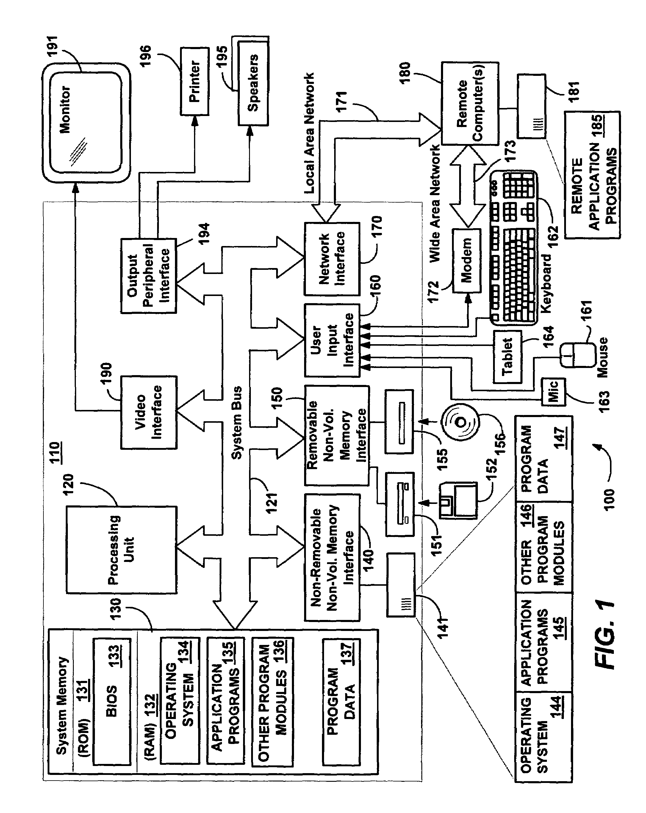
[0039]FIG. 1 illustrates an example of a suitable computing system environment 100 on which the invention may be implemented. The computing system environment 100 is only one example of a suitable computing environment and is not intended to suggest any limitation as to the scope of use or functionality of the invention. Neither should the computing environment 100 be interpreted as having any dependency or requirement relating to any one or combination of components illustrated in the exemplary operating environment 100.

[0040]The invention is operational with numerous other general purpose or special purpose computing system environments or configurations. Examples of well known computing systems, environments, and / or configurations that may be suitable for use with the invention include, but are not limited to, personal computers, server computers, hand-held or laptop devices, multiprocessor systems, microprocessor-based systems, set top boxes, progr...


PUM


Abstract

A system and method for discovering network topology by various switch training and probing methods. Segments are discovered by having computers enter a promiscuous mode and determining from packets sent to a selected computer which computers see which other computers in the network. From the segments, various switch interconnections are determined, by having different computers train switches as to a training address and seeing which computers receive probe packets sent to that training address from another computer. Various training and probing methods are described that locate intermediate segments, deep switches, switch interconnections, and edge and singleton cases. In one implementation, a master computer coordinates the other computers (and devices) in the network to send the training and probing packets, and report on received packets, in order to determine the network topology.

Description

FIELD OF THE INVENTION[0001]The present invention is generally directed to computer systems and networks, and more particularly to network topology.BACKGROUND OF THE INVENTION[0002]Network topology discovery is the practice of mapping a network to discover a graph representing hosts (e.g. computer systems), network elements (e.g. routers or switches), and the various interconnections between them. Topology discovery can be at a variety of levels ranging from Internet-scale mapping efforts to small-scale home area networks. However, the techniques applicable to one effort are not necessarily transferable to others. Further, the amount of support for topology discovery provided by the network elements also varies. For example, network elements typically found in the home area provide minimal or no support, while enterprise Local Area Networks (LANs) usually include Simple Network Management Protocol (SNMP)-capable switches that allow their own knowledge about the topology of the netwo...

Claims


Application Information

Patent Timeline
Patent Type & Authority Patents(United States)
IPC IPC(8): H04L12/28G06F15/173H04L12/24H04L12/26H04L12/46H04L12/56
CPCH04L12/462H04L41/12H04L45/26H04L45/02H04L12/2697H04L41/0213H04L43/0882H04L43/50H04L43/0829
Inventor BLACK, RICHARDDONNELLY, AUSTINFOURNET, CEDRIC
Owner MICROSOFT TECH LICENSING LLC
Why Eureka
Try Eureka