
Single transceiver architecture for a wireless network

a wireless network and single-transceiver technology, applied in the field of single-transceiver architecture for wireless networks, can solve the problems of choppy video image, more problematic transmission of high-bandwidth video programs, and one of the most unreliable of all the networking options available for home media networks

Active Publication Date: 2009-07-28
SONY INTERACTIVE ENTRTAINMENT LLC +3
View PDF108 Cites 78 Cited by
  • Summary
  • Abstract
  • Description
  • Claims
  • Application Information

AI Technical Summary

Benefits of technology

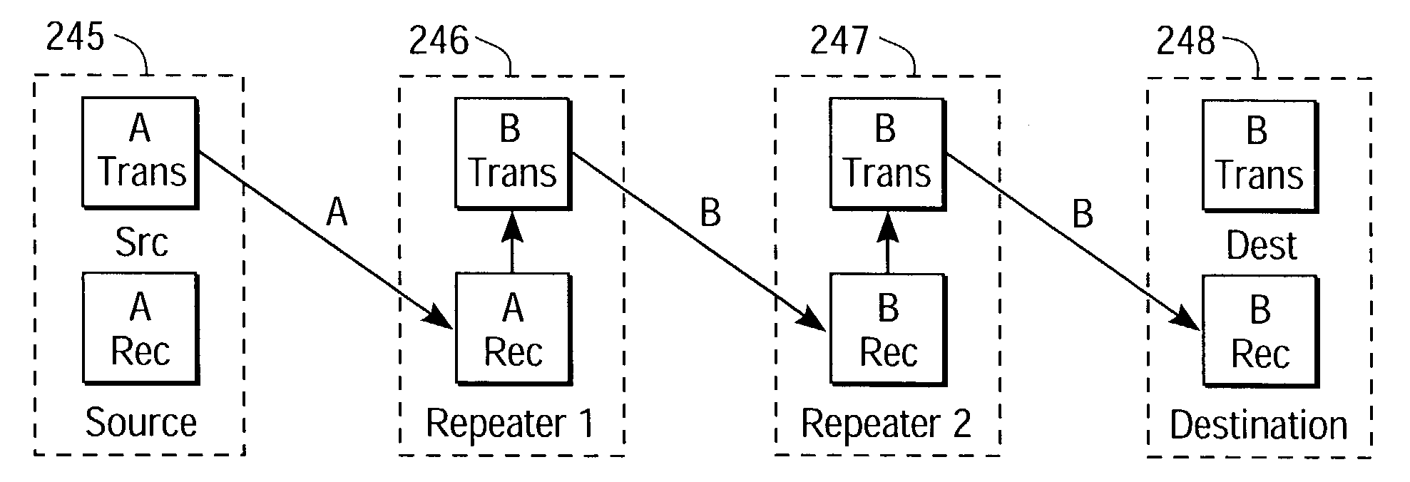
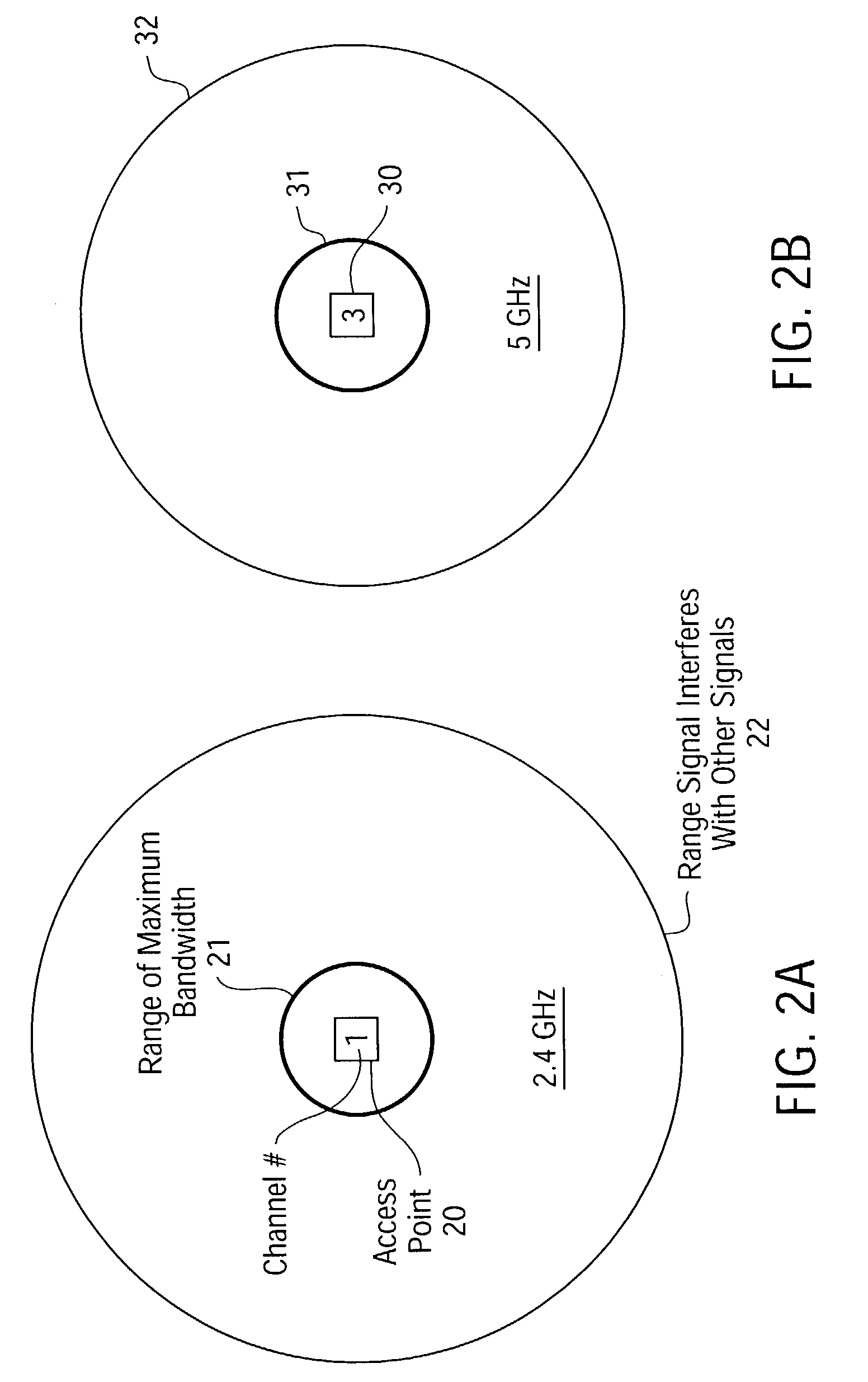
The solution achieves unlimited range extension with full bandwidth preservation, supporting multiple simultaneous video streams at high data rates (up to 30 Mbps) by using multiple access points on non-overlapping channels, reducing interference and maintaining signal quality across a building.

Problems solved by technology

Although traditional wireless networks work fairly well for residential Internet traffic running at data rates below 1 megabit per second (Mbps), transmission of high-bandwidth video programs is more problematic due to the much faster video data rates.
Degradation of the video signal can also lead to repeated transmission re-tries, causing the video image to appear choppy.
These practical limitations make present-day wireless technologies one of the most unreliable of all the networking options available for home media networks.
The drawback of this approach, however, is that it requires that cable wires be routed through the interior of the structure.
But the problem with these types of wireless repeaters is that they retransmit at the same frequency as the primary access point device.
For example, if a data packet needs to be repeated (i.e., re-transmitted) three times in the same channel, each packet must wait until the previous packet has been repeated which means that the resulting bandwidth loss is 67%.
Naturally, with more repeaters, more data hops are required, so the bandwidth loss becomes worse.
This approach basically trades-off bandwidth for signal range—extending the range of the wireless network, but sacrificing valuable bandwidth in the process.
The main drawback with compression / decompression techniques is that they tend to compromise the quality of the video image, which is unacceptable to most viewers.
This approach also suffers from the problem of lost connections during transmission.

Method used


Image

  • Single transceiver architecture for a wireless network
  • Single transceiver architecture for a wireless network
  • Single transceiver architecture for a wireless network

Examples


Embodiment Construction

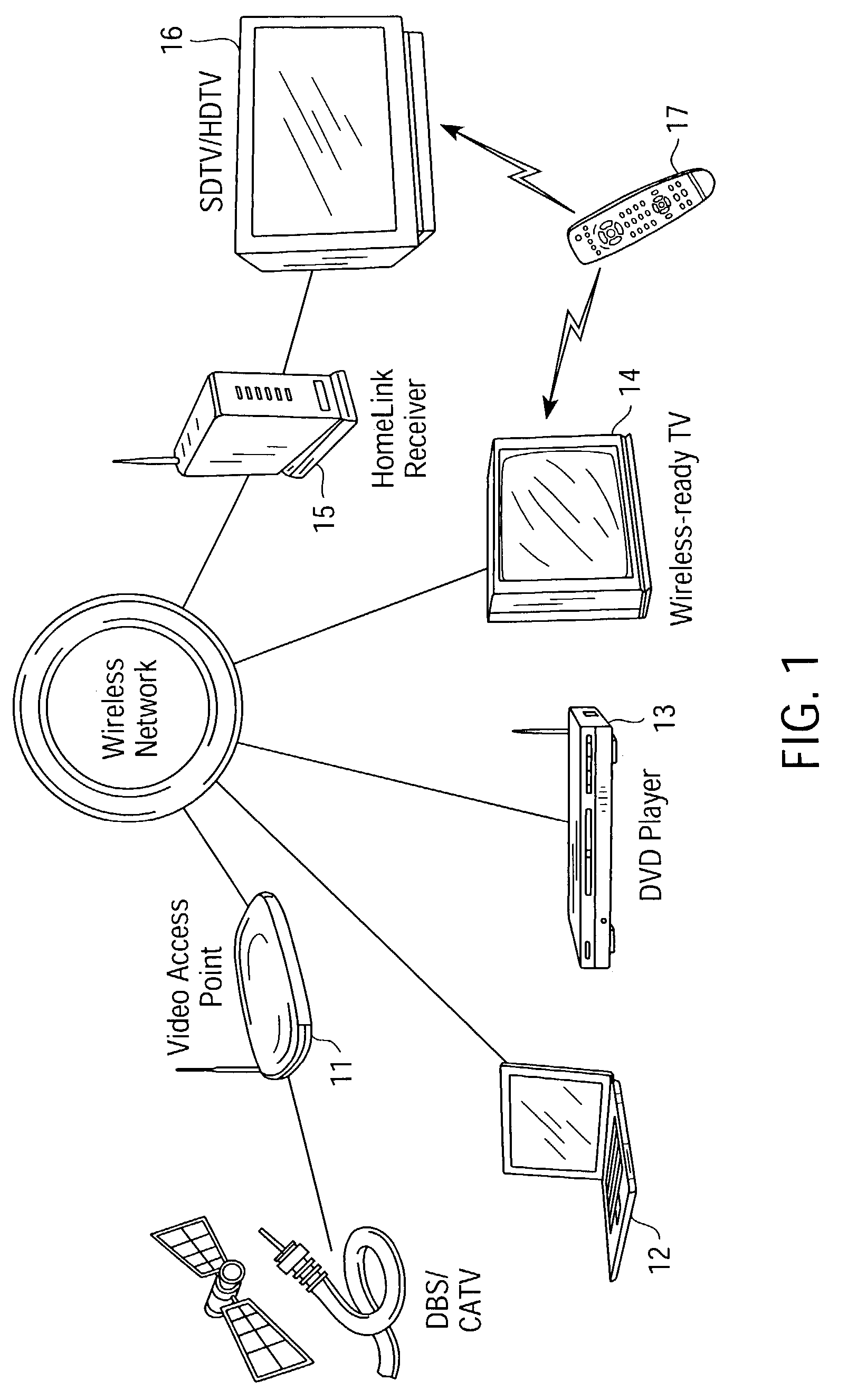
[0043]The present invention is a wireless local area network (WLAN) that utilizes cellular techniques to extend the range of transmission without degrading bandwidth. The wireless network of the present invention is thus ideally suited for transmitting video programs (e.g., digitally-encoded video broadcast services, pay-per-view television, on-demand video services, etc.) throughout a house or other building, thereby creating a “media-live” environment.

[0044]In the following description numerous specific details are set forth, such as frequencies, circuits, configurations, etc., in order to provide a thorough understanding of the present invention. However, persons having ordinary skill in the communication arts will appreciate that these specific details may not be needed to practice the present invention. It should also be understood that the basic architecture and concepts disclosed can be extended to a variety of different implementations and applications. Therefore, the follow...


PUM


Abstract

A network for wireless transmission of data includes a source access point, a destination device and a plurality of wireless repeaters that provide a transmission link between the source access point and the destination device. The plurality of access points each includes a single transceiver with separate transmitter and receiver sections operable to simultaneously transmit and receive data on different frequency channels. It is emphasized that this abstract is provided to comply with the rules requiring an abstract that will allow a searcher or other reader to quickly ascertain the subject matter of the technical disclosure. It is submitted with the understanding that it will not be used to interpret or limit the scope or meaning of the claims. 37 CFR 1.72(b).

Description

RELATED APPLICATIONS[0001]This application is a continuation-in-part application of Ser. No. 10 / 367,197 filed Feb. 14, 2003 entitled, “SELF-CONFIGURING, ADAPTIVE, THREE-DIMENSIONAL, WIRELESS NETWORK”. FIELD OF THE INVENTION[0002]The present invention relates generally to wireless networks, and more particularly to methods and apparatus for configuring, expanding and maintaining a wireless network for home or office use.BACKGROUND OF THE INVENTION[0003]In recent years, wireless networks have emerged as flexible and cost-effective alternatives to conventional wired local area networks (LANs). At the office and in the home, people are gravitating toward use of laptops and handheld devices that they can carry with them while they do their jobs or move from the living room to the bedroom. This has led industry manufacturers to view wireless technologies as an attractive alternative to Ethernet-type LANs for home and office consumer electronics devices, such as laptop computers, Digital V...

Claims


Application Information

Patent Timeline
Patent Type & Authority Patents(United States)
IPC IPC(8): H04J1/10H04B7/26H04L12/28H04L12/56H04L29/06H04W88/08
CPCH04W88/08H04L63/0428H04B7/2606
Inventor PERLMAN, STEPHEN G.
Owner SONY INTERACTIVE ENTRTAINMENT LLC
Learn More